Documentation XFEM4U: Difference between revisions
Jump to navigation
Jump to search
Tag: visualeditor |
|||
| (283 intermediate revisions by 2 users not shown) | |||
| Line 1: | Line 1: | ||
__NOTOC__ | |||
[[Main Page | BACK]] | |||
===Introduction=== | ===Introduction=== | ||
This page contains the documentation of [[XFEM4U]]. It is meant as a full description of all functions and possibilities of the program. | This page contains the documentation of [[XFEM4U]]. It is meant as a full description of all functions and possibilities of the program. | ||
Other relevant information about XFEM4U can be found in the following links: | Other relevant information about XFEM4U can be found in the following links: | ||
* [[Tutorials XFEM4U]] | * [[Tutorials XFEM4U]] | ||
* [[XFEM4U | Full list of features of XFEM4U]] | * [[XFEM4U |Full list of features of XFEM4U]] | ||
* [[Example Projects]] | * [[Example Projects]] | ||
===Release Notes=== | ===Release Notes=== | ||
Release notes of XFEM4U: [https://software.struct4u.com/downloads/XFEM4U/Release_notes_XFEM4U_en.pdf link] | |||
=== | ===Features and limitations=== | ||
Full list of features of XFEM4U can be found [[XFEM4U | here.]] | Full list of features of XFEM4U can be found [[XFEM4U | here.]] | ||
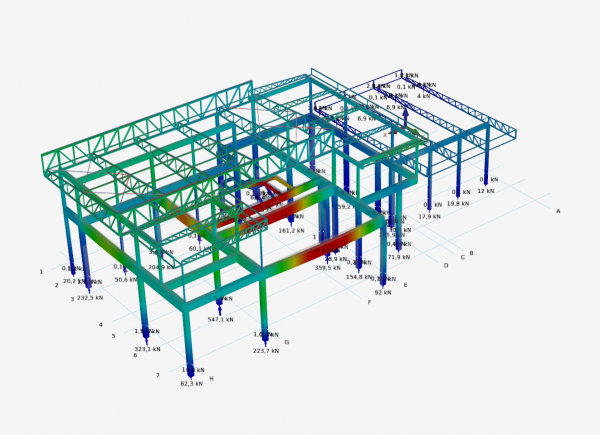
[[File:Residential Steel Trusses Roof_3.png |600px]] | |||
===Chapters user manual=== | |||
[[Get started with the Struct4U Engineering Tools | 1. Get Started]] | |||
[[XFEM4U UI | 2. Basic concept User Interface]] | |||
[[Struct4U Design Arrangements | 2.1 Design Arrangements and coordinates]] | |||
'''3. Export/Import''' | |||
[[Autodesk Revit/Dynamo | 3.1 Autodesk Revit/Dynamo]] | |||
[[Tekla Structures | 3.2 Tekla Structures]] | |||
[[XML Interface | 3.3 XML Interface]] | |||
[[DWG/DXF | 3.4 DWG/DXF]] | |||
[[SDNF| 3.5 SDNF]] | |||
'''4. Geometry''' | |||
[[XFEM4U Nodes | 4.1 Nodes]] | |||
[[XFEM4U Supports | 4.2 Supports]] | |||
[[XFEM4U Beams | 4.3 Beams]] | |||
[[Profile| 4.4 Section/Profile]] | |||
[[XFEM4U Plates | 4.5 Plates]] | |||
[[XFEM4U Grid Lines/ levels | 4.6 Grid lines/levels]] | |||
[[XFEM4U Outer Panels | 4.7 Outer Panels]] | |||
[[XFEM4U Hall Wizard | 4.8 Hall Wizard]] | |||
'''5. Loads''' | |||
[[XFEM4U Load Cases | 5.1 Load cases]] | |||
[[XFEM4U Load Combinations | 5.2 Load combinations]] | |||
[[XFEM4U Loads | 5.3 Loads]] | |||
[[XFEM4U Load generator | 5.4 Load generator]] | |||
'''6. Analysis & Design''' | |||
[[XFEM4U Analysis | 6.1 Calculation settings]] | |||
[[Documentation Eurocode | 6.2 Eurocode Steel & Timber Design]] | |||
[[XFEM4U Eurocode RC | 6.3 Eurocode Reinforced Concrete Design]] | |||
[[Eurocode Steel Connections | 6.4 Eurocode Steel Joint Design]] | |||
'''[[Documentation ANSI | 7. Building Code ANSI]]''' | |||
'''8. Display calculation results''' | |||
[[XFEM4U Display Results | 8.1 Display results]] | |||
[[XFEM4U Analysis | 8.2 Calculation settings]] | |||
[[Struct4U Optimization | 8.3 Optimization]] | |||
'''9. UI and other settings''' | |||
[[XFEM4U Edit | 9.1 Edit]] | |||
[[XFEM4U Selection | 9.2 Selection]] | |||
[[XFEM4U View | 9.3 View ]] | |||
[[ | [[XFEM4U Display Options | 9.4 Display options]] | ||
[[Struct4U Dockable Windows | 9.5 Dockable windows]] | |||
[[Struct4U Changing Dimensions | 9.6 Changing dimensions]] | |||
[[ | [[XFEM4U Menu | 9.7 Menu]] | ||
[[XBeam2D XFrame2D Preferences | 9.7.1 Preferences]] | |||
[[ | [[XBeam2D XFrame2D Drawing| 9.7.2 Drawing]] | ||
[[XBeam2D XFrame2D Snap options| 9.7.3 Snap options]] | |||
[[XBeam2D XFrame2D Regular grid| 9.7.4 Regular grid]] | |||
[[ | [[XBeam2D XFrame2D Output| 9.7.5 Output]] | ||
[[XBeam2D XFrame2D User defined profiles| 9.7.6 User defined profiles]] | |||
[[XBeam2D XFrame2D Preview | 9.7.7 Preview]] | |||
[[XFEM4U Backup files | 9.8 Backup files]] | |||
[[XFEM4U Context menu | 9.9 Context menu]] | |||
'''10. Background information about calculations''' | |||
[[XBeam2D Deflection Calculation | 10.1 Deflection]] | |||
[[Struct4U tapered section| 10.2 Tapered section]] | |||
[[Background Information and Theory | 10.3 Background steel & timber Eurocode]] | |||
[[FEM best practices and examples | 10.4 Finite Element Mesh & Solver]] | |||
[[XFEM4U UI and settings | 11. UI and other settings]] | |||
Latest revision as of 20:13, 11 November 2022
Introduction
This page contains the documentation of XFEM4U. It is meant as a full description of all functions and possibilities of the program. Other relevant information about XFEM4U can be found in the following links:
Release Notes
Release notes of XFEM4U: link
Features and limitations
Full list of features of XFEM4U can be found here.
Chapters user manual
2. Basic concept User Interface
2.1 Design Arrangements and coordinates
3. Export/Import
4. Geometry
5. Loads
6. Analysis & Design
6.2 Eurocode Steel & Timber Design
6.3 Eurocode Reinforced Concrete Design
6.4 Eurocode Steel Joint Design
8. Display calculation results
9. UI and other settings
10. Background information about calculations
10.3 Background steel & timber Eurocode
