Documentation XFEM4U
Introduction
This page contains the documentation of XFEM4U. It is meant as a full description of all functions and possibilities of the program. Other relevant information about XFEM4U can be found in the following links:
Release Notes
Releasenotes of XFEM4U: [link]
Possibilities and limitations
Full list of features of XFEM4U can be found here.
Chapters user manual
2. Basic concept User Interface
2.1 Design Arrangements and coordinates
5.1.1 Eurocode Steel Joint Design
5.2 Eurocode Reinforced Concrete Design
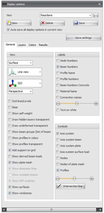
Display options
Views
Optional an unlimited number of views can be made. The camera position and all display settings will be stored per view. All views are also saved in the project file input file so that they can be displayed and or included in the output again when the project is reopened. You can of course rename all views. In the output selection you can select the views to be included in the output. All 3d view image of Geometry Loads and Results are automatically placed in the right place. When generating output all selected 3d view images are also saved as a png-file in the map where the project file input file is saved.
View
You can change the view. Name of the view can be adjusted here.
A separate dialog box is displayed where you can change the order of all created views.
Add a new view. The default name is "View 1", "View 2", ... and so on.
