Parametric Design and Python
Introduction
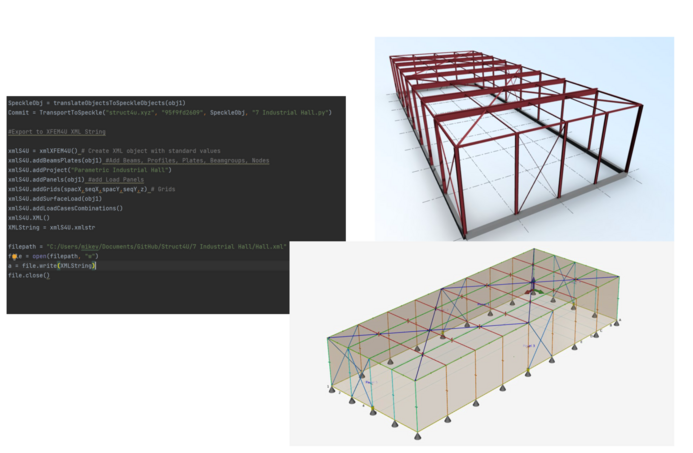
This page contains information about Parametric Design in XFEM4U and how you can create 3D-models using Python.
We can send these models to Speckle or to XFEM4U. On this github repository you can find some examples of this using buildingpy.https://github.com/DutchSailor/Struct4U

Direct Commands
Within XFEM4U and XFrame2D there is a function called 'DirectCommands'. You can use DirectCommands to open XFEM4U and XFrame2D from an external program like Excel or Python.
In this page you can find examples how to use this.
Python
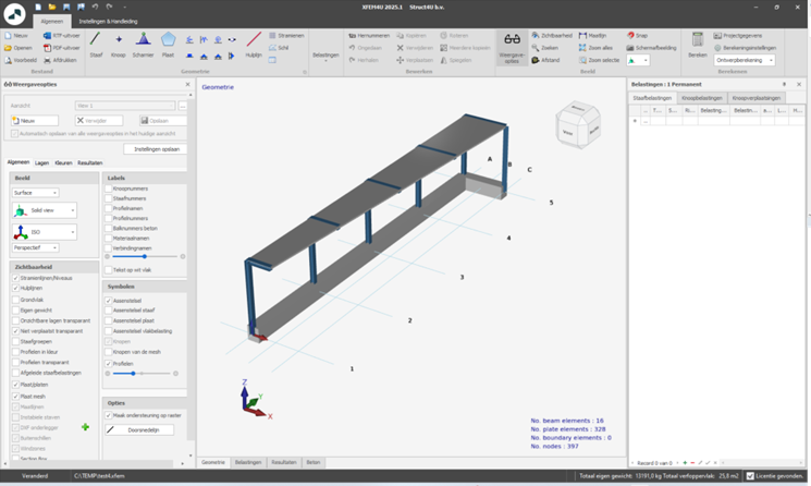
This example shows how to create a 3D-model in XFEM4U using Python. We use the open source Python Interpreter PyCharm Community Edition. You can download PyCharm here.
We use the opensource library BuildingPy. In this library there are classes like point, vector, line, polycurve, panel, beam, support, loads etcetera. From this library we create objects for our 3D-model.
Examplefiles can be downloaded on github using this link.
Example 1
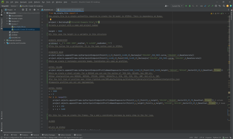
This is the Pythoncode in PyCharm.
Below the Pythoncode with comments included per line of code.
from bp_single_file import *
#bp_single_file is a single pythonfile required to create the 3D-model in XFEM4U. THere is dependency on Numpy.
project = BuildingPy("Struct4U Example file","0")
#create a project with a name and project number
height = 3000
#In this case the height is a variable in this structure
#CREATE GRIDSYSTEM
gridinput = ["0 1000 1000",seqChar,"0 4x3600",seqNumber,"0"]
#This the syntax for a gridsystem. It is the same syntax used in XFEM4U.
#CONCRETE BEAM
project.objects.append(Frame.byStartpointEndpoint(Point(0,0,0),Point(0,14400,0),Rectangle("350x500",350,500).curve,"350x500",0,BaseConcrete))
project.objects.append(Frame.byStartpointEndpoint(Point(0,14400,0),Point(2000,14400,0),Rectangle("350x500",350,500).curve,"350x500",0,BaseConcrete))
#Here we create 2 rectangle concrete beams. Coordinates are used an profiles.
#STEEL COLUMN
project.objects.append(Frame.byStartpointEndpointProfileNameShapevector(Point(2000,14400,0),Point(2000,14400,height),"HEA160","HEA160",Vector2(0,0),0,BaseSteel,"Frame"))
#Here we create a steel column. For a HEA160 you can use the syntax of 'HEA 160, HE160A, hea 280 etc.
#Other steelprofiles are HEB100, HEM100, IPE100, 100AA, HD260/54,1, DIN, DIE, DIR, DIL, UNP, B42.4/2.6, INP.
#For the full list of profiles see: https://github.com/3BMLabs/building.py/blob/main/library/profile_database/steelprofile.json
#Composite profiles are not yet implemented.
#STEEL FRAMES
x = 1000
y = 0
for i in range(5):
project.objects.append(Frame.byStartpointEndpointProfileNameShapevector(Point(0,y,0),Point(0,y,height),"HEA180","HEA180",Vector2(0,0),90,BaseSteel,"Frame")) # column
project.objects.append(Frame.byStartpointEndpointProfileNameShapevector(Point(0,y,height),Point(x,y,height),"HEA180","HEA180",Vector2(0,0),0,BaseSteel,"Frame")) # beam
x = x + 250
y = y + 3600
#In this for loop we create the frames. The x and y coordinate increase by every step in the for loop.
#LOADS
#PLATE IN XFEM4U
project.objects.append(Panel.byPolyCurveThickness(
PolyCurve.byPoints(
[Point(0,0,height),
Point(0,14400,height),
Point(2000,14400,height),
Point(1000,0,height),
Point(0,0,height)]),
100,
0,
"Plate"
,BaseConcrete.colorint))
#The code above is used to create a plate based on 5 coordinates. The plate has a thickness.
#SEND PROJECT TO SPECKLE
#project.toSpeckle("31d9948b31")
#It is possible to visualize the result of this parametric structure in Speckle.
#CREATE XML-FILE
pathxml = "C:/TEMP/test4.xml"
#This is the path were the temporary file is saved.
createXFEM4UXML(project,pathxml,gridinput)
#We create a XML to load into XFEM4U.
OpenXMLXFEM4U(pathxml)
#This function will activate XFEM4U and open the parametric model

