New features
This page contains the new features within the Struct4U Engineering Tools. Only the main new features are noticed.
XFrame2D, XBeam2D 2024.2 september 2023
Improved UI
XML Import/Export including bar loads and node loads. This is a very useful tool for manufacturers and suppliers with repetitive structural calculations. These can be controlled via Python, Excel or an external program
Grid and level functionality has been improved
Bar loads can be graphically adjusted and dragged better
Spy improved
Pan, zoom, copy and arrays now works like XFEM4U and takes less clicks
XFEM4U 2024.3 september 2023
XFEM4U 2024.3
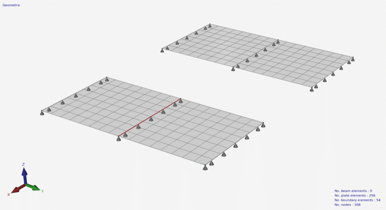
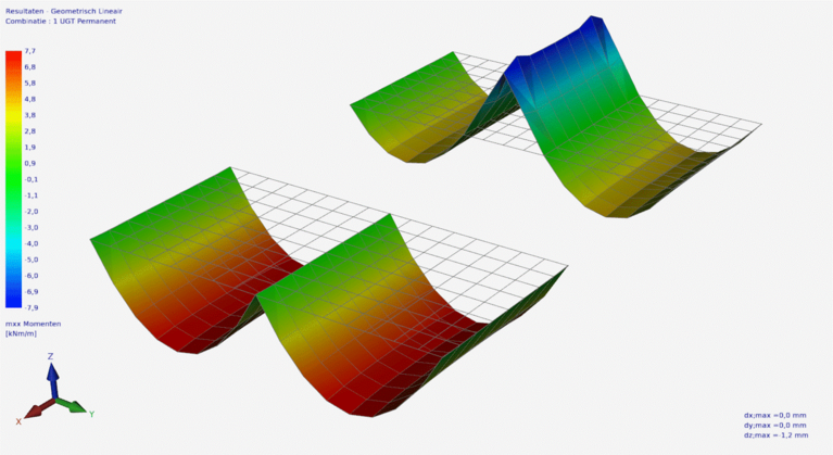
Hinged connection in plates
Plate elements were always calculated as continuous and moment fixed. New is that plate edges can be entered and calculated as hinged.
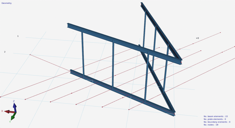
Improved graphical input of bar loads using dimension lines
Draw guide lines
It is possible to enter drawing guide lines. Guide lines can be very convenient when entering your construction. A display option has been added so you can show or hide these guide lines.
New look and feel user interface
The user interface has a new look and feel. Modern and functional. We are now using the new "skin" "The Bezier" which renders its elements with vectors. This means resolution independence and sharp rendering on Hi-DPI displays. This is not only nice to work with but also less tiring. It is also possible to set the colors yourself. The menu will contain more items. To keep it clear for the user, the menu groups Geometry and Loads are automatically minimized depending on which tab is active. All to make the user-friendliness of the software even better.
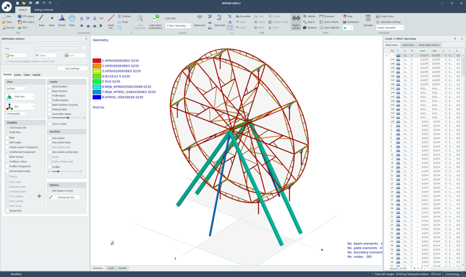
Improved display options
Display option: The color scale profiles now list the material name after the profile name.
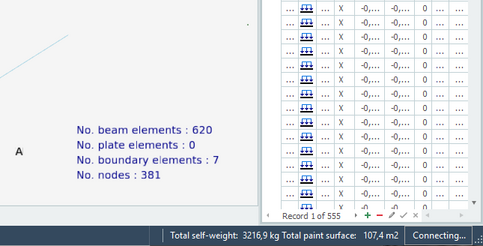
The Geometry tab displays information about the model (number of beams, plates, etc.) right at the bottom.
Improved plates entry
Plates/walls: The entry has been modified. Now the dialog box will be displayed on closing the contour line. This way of working is more intuitive. And it also means that, among other things, the mesh size can be set or adjusted directly.
Improved concrete module
Struct4U Engineering Tools 2024.2 03-07-2023
XFEM4U 2024.2
Elastic supporting beams / beams on an elastic soil.
It is possible to specify an elastic soil for each beam. The elastic soil is schematized as a series of springs that can only absorb positive reactions. Possible "loosening" is therefore provided. The spring spacing can be influenced. The modulus of subgrade reaction (kN/m3 ) is automatically converted to springs with the appropriate spring value (kN/m). The generated springs are drawn transparently.
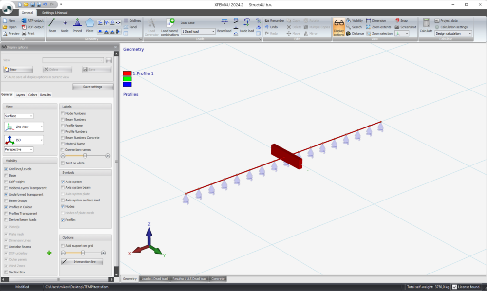
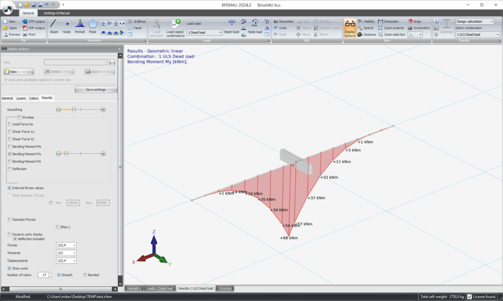
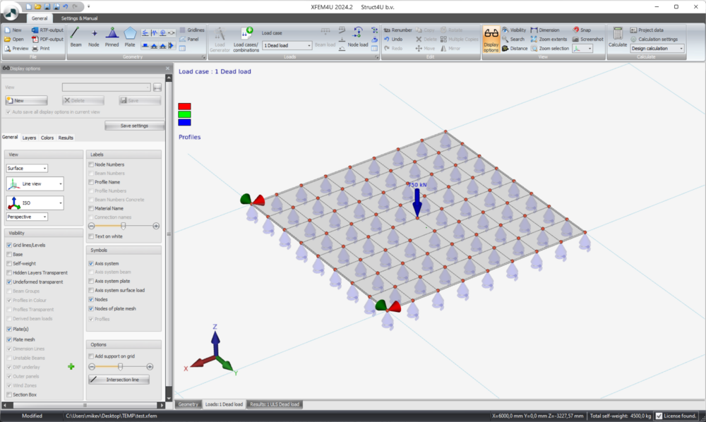
Representation of elastic soil under plate
For plates on an elastic soil, the generated springs are drawn transparently per mesh node. In the view options, turn on "Node of plate mesh" to have all springs drawn. The elastic soil can be displayed properly that way.
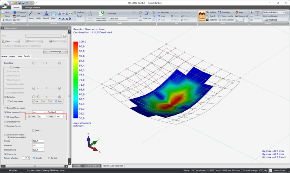
Display of plate stresses and forces
It is now possible to display values within a certain range by entering the maximum and/or minimum value. For example, you can display only those elements with a bending stress greater than 100 N/mm2.
Surface loads
It is checked whether the surface load falls into a plate. If so, no beam loads are generated. However, the detection of whether a surface load fell into a plate was not good which in some cases also resulted in no beam loads being generated. This has been resolved. (helpdesk #1829)
XFrame2D 2024.1, XBeam2D 2024.1
Load generator
It is now possible to enter the base wind velocity Vb0 for other countries so that wind loads can be generated.
Our profile database has expanded the old steel profiles DIN, DIE, DIL and DIR.
XConstruct 2024.1
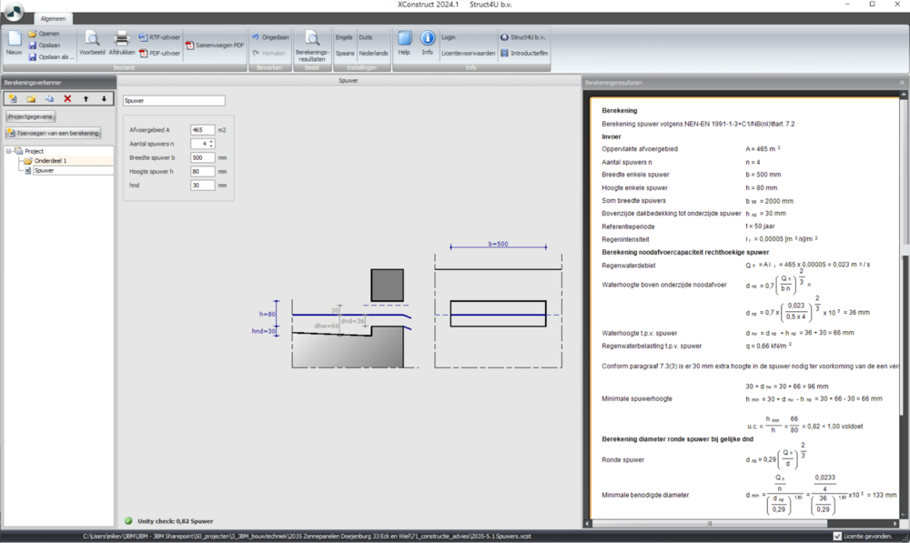
Roof spigot
Calculation of a roof spigot is added as a new module.
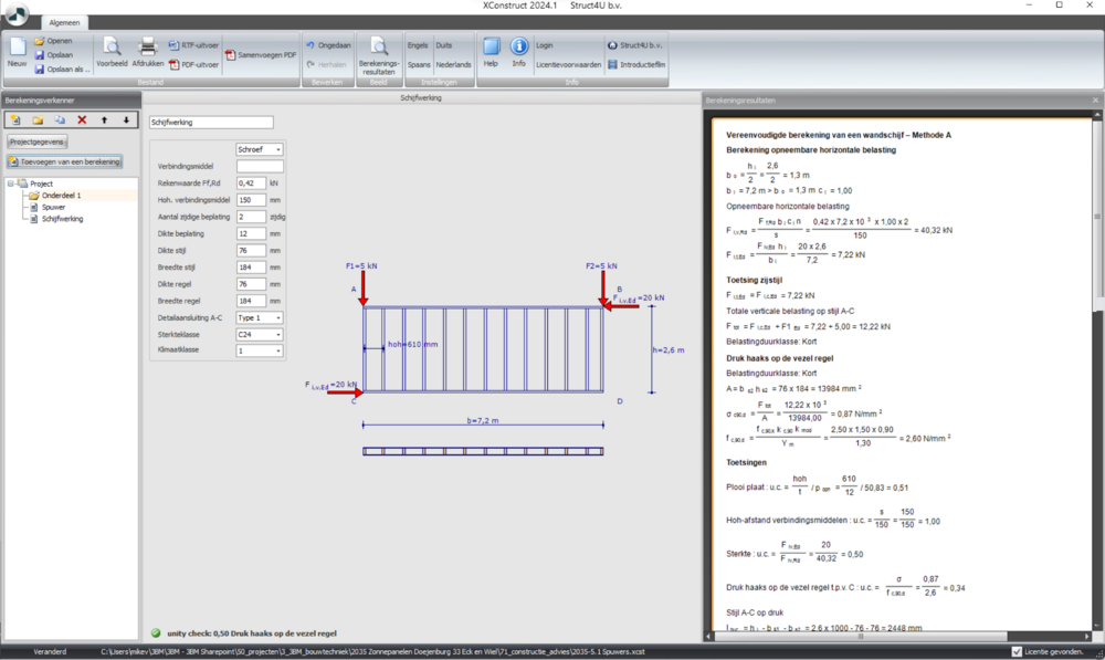
Wood Framing Wall Stability check
is added as a new module. With this module you can quickly test the stability of your wood framing wall. This module contains the calculation of a wall according to Method A of the Eurocode 5 H 9.2.4.2. With this method you can test the shear strength of an HSB wall.
General
The Error handler has been improved which leads to more stable programs.
Struct4U Engineering Tools 2024. 20-04-2023
Ponding
It is now possible to calculate ponding of structures in 3D in XFEM4U.
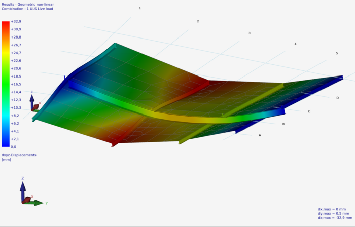
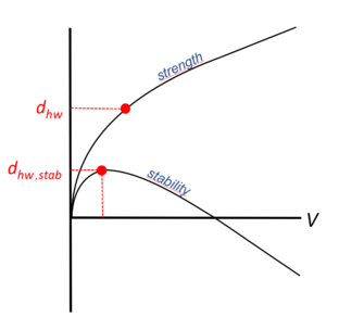
We are currently working on a proper documentation and instructions which will soon be available.
Orthotropic Plates
Orthropic Plates can be now be calculated.
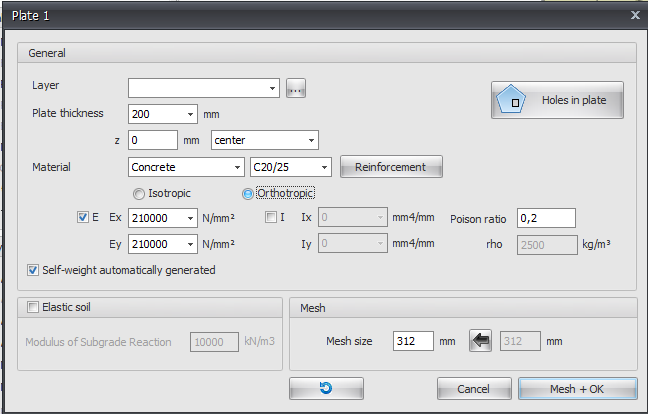
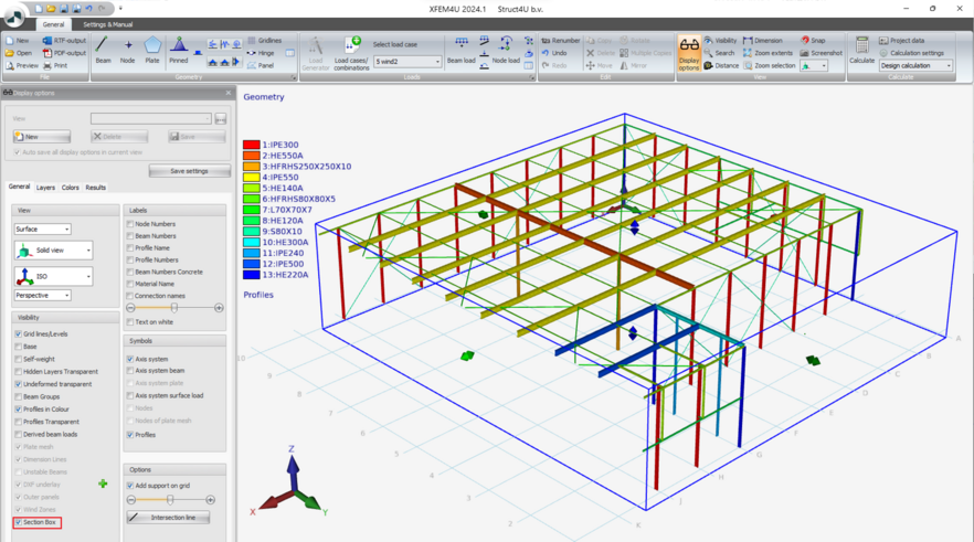
Section Box
As in Autodesk Revit, you can use a Section Box to limit the visibility of the model. The objects of the model inside the section box are still visible, what is outside it is no longer visible.
Match properties
(a new right-click function) Match properties allows you to quickly and easily copy all beam data from a selected beam.
The cursor changes. Now click on the other beam to copy that data. Right-click or ESC disables this function.
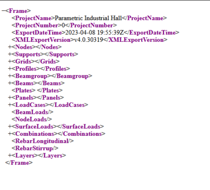
XML-Export improved
The XML-export and XML-import has been expanded. Now you can export and import Panels, Load Cases, Beam Loads, Node Loads, Surface Loads and Load Combinations.
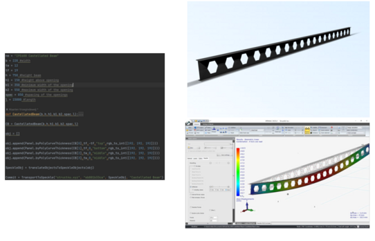
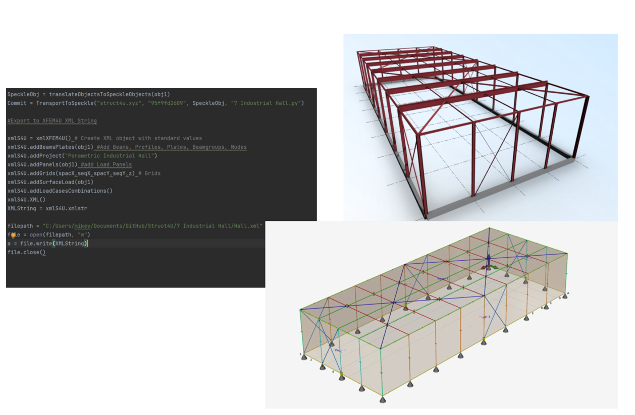
Struct4U Python Examples
With the Struct4U Speckle Server and the XML-interface in XFEM4U we can create parametric models using Python.
We can send these models to Speckle or to XFEM4U. On this github repository you can find some examples of this using buildingpy.https://github.com/DutchSailor/Struct4U
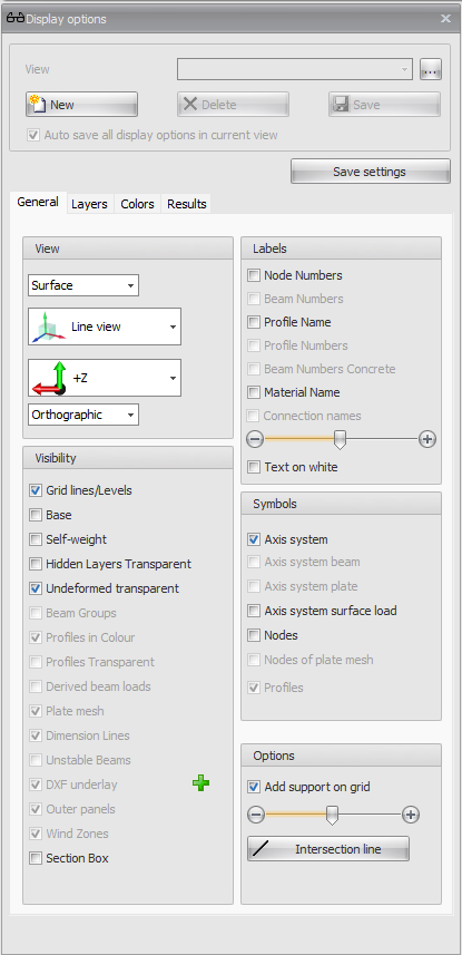
Display options
The display options window is restructured and improved. The functions are ordered per category.
Speckle 3D
At Struct4U we have our own Speckle Server. https://www.struct4u.xyz More information about Speckle can be found here: https://speckle.systems/
You can create a free account on our server and use it to share models with clients or other participants within the design proces.
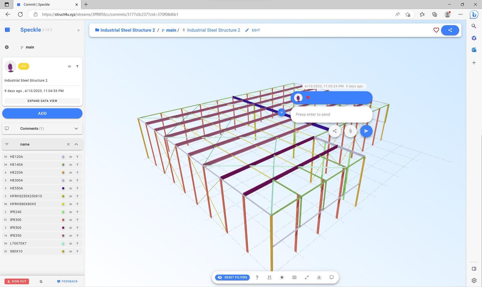
Have a look at this example model: https://struct4u.xyz/streams/3fff8f56cc/commits/3177c0c237
Hinged connection in plates
Meshing plates
Plate meshing has been greatly improved in a number of aspects.
DXF Underlay
- In the view options a button has been added to add the DXF underlay immediately. An existing overlay can also be deleted with the same button. (helpdesk #1683)
- You can move and rotate a DXF underlay. Often the coordinate system in the DXF file is different than in your model. So now you can move and rotate it. (helpdesk #1730)
License Server
To make communication via our web API with our License Server even more secure, TLS 1.2 (Transport Layer Security) is now being used. (helpdesk #1737)
Snap perpendicular
Other Improvements
- In the graphic you could already display the (Min./Max.) reaction forces. What is new is that you can now display the (Min.) reaction forces and/or the (Max.) reaction forces. (helpdesk #1691) For new projects, the snapsize is read in from the ini file. (helpdesk #1681)
- The snapsize can also be read from the XML file. (helpdesk #1681)
- When the display options was turned off it could not be opened. An error message "The dock manager is not yet initialized" appeared. This has been resolved. (helpdesk #1710/#1711)
- Load generator - snow load: The roof pitch was not properly determined resulting also in mu1 and subsequently snow load. For steep roofs, this caused the magnitude of snow load to be too high (conservative). This has been solved. (helpdesk #1716)
- The torsional moment of inertia Ix for rectangular cross section was not properly determined. This has been resolved. (helpdesk #1720)
- Surface loads: Selecting surface loads has been improved. When you click on one of the components, all are selected as a "block".
- Q beam load: Selecting the q load has been improved. Clicking on any of the components will select all as a "block"
- Large shear forces developed in a tapered profile. The cause: A tapered profile is approximated by dividing it into a number of sub beams, each with a different moment of inertia. A beam is also divided when nodes are found on the beam. In this case, it occurred that the nodes generated were too close to existing nodes, making the partial beams very short and causing computational problems. This was solved by checking that the nodes to be generated do not get too close (within snap distance) to existing nodes. (helpdesk #1738)
- Adding a plate: When you ended drawing a plate after entering 1 or 2 nodes with the right mouse button, the program hung. This has been fixed. (helpdesk #1451 en #1734)
- You could already set the number of decimals of forces and displacements. The sum of forces and largest displacements (bottom right of the screen) did not change with it. This has been solved. (helpdesk #1416)
- On the Load tab, it could happen that you unintentionally deleted also a beam, for example, due to a wrong selection. This has been improved. Now the question is always asked when you did not select only loads. (helpdesk #1754)
- For a large number of combinations, the table combinations was not printing correctly in all cases. This has been resolved. (helpdesk #1756)
- When using the "Hinge" menu option, the beam load(s) were not split properly. For example a q-load was running through across the 2 beams causing erroneous mechanics results. This has been resolved. (helpdesk #1763)
- A serious error was found with a surface load on a roof surface at exactly 45 degrees. Mathematically, the sign of the load flipped, causing the load to be in the wrong direction. This error has been corrected. (helpdesk #1766)
- After a zoom selection the selection remained. This has been improved.
- XML import: Import of nodes was not quite correct. This has been improved.
- In specific cases beam and node numbers of transparent drawn beams were shown. This has been improved. Beam and node numbers are never shown when the beam itself is drawn transparent. (helpdesk #1775)
- When joining nodes within the snap distance (CheckOnCoincidingNodes function), the cross-sectional size of the connecting beams in the node is now considered. In this way, the nodes of the main supporting structure are given more priority (weight). (helpdesk #1789)
- For views of grids and levels, the remaining beams were drawn transparently. For large construction, this was not clear. This has been improved. Now other beams are no longer drawn transparently. You can still show them by enabling "Draw hidden layers layers transparent". (helpdesk #1782)
- Meshing of plates: When the nodes of the plate contour were not completely in a plane, the mesh nodes were not taken together with the nodes of the plate contour. This has been improved. The testing of the distance between nodes has been increased from 1 mm to 5 mm. (helpdesk #1799)
- When you copy a beam with the function Visibility switch on the new beam is not drawn visible. This has been fixed. (helpdesk #1804)
- Plates: The modulus of elasticity at material Other could not be adjusted. This has been resolved. (helpdesk #1802)
- Snapping to beams has been further extended to include a snap to the intersection with the lines of the DXF underlay, and the grid lines. (helpdesk #1764)
- When a plate is removed and re-entered, all data (slab thickness, concrete grade, etc.) is remembered. (helpdesk #1753)
- A triangular plate was not drawn as solid. This has been fixed. (helpdesk #1736)
- Concrete: The determination of the maximum value in the color scale of the reinforcement quantities (Asxt, Asyt, Asxb, Asyb and Asw) did not examine whether the plates (using layers) were visible or not. This has been improved. (helpdesk #1742)
- Steel When the steel standard was off in the calculation settings, the program broke down when printing the yield strength. This problem has been resolved. (helpdesk #1697)
- Steel In specific cases, reduction factor for lateral-torsional buckling χLT could become greater than 1.00. This is obviously not possible and has been adjusted. (helpdesk #1745)
- Steel Beam-column moment connection - butt joint: The stiffness of the end plate was charged 1x instead of 2x. This has been resolved. (helpdesk #1666)
- Steel Beam-column moment connection - butt joint: In the stiffness calculation the bolt length was not correctly determined This is solved. (helpdesk #1667)
- Steel Beam-column moment connection - butt joint: In the stiffness calculation a stiffness modification factor of 2 instead of 3 was used.
- Timber Columns were also always tested according to Art. 6.2.4. This turned out to be incorrect. Formulas (6.19) and (6.20) should be used only when lambda;rel,z < 0.3 and lambda;rel,y < 0.3. This has been fixed. (helpdesk #1698)
Struct4U Engineering Tools 2023.2 09-11-2022
| Feature | Image |
|---|---|
| The American steel standard ANSI/AISC 360-16 has been implemented. |
Struct4U Engineering Tools 2023. 1 04-11-2022
On 3 November 2022 we have released new versions of the Struct4U Engineering Tools 2023!
| Feature | Image | |
|---|---|---|
| The American steel standard ANSI/AISC 360-16 has been implemented. | 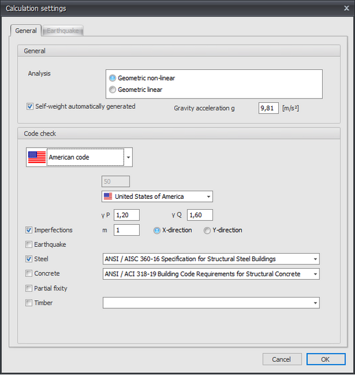 | |
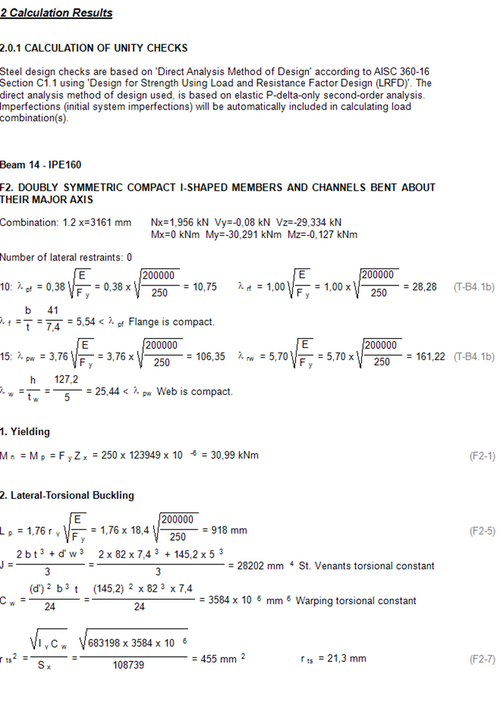
| The output of the steel calculation of the ANSI/ASIC 360-16 is implemented in detail
in the calculation results including all the formulaes of the standard. |
 | |
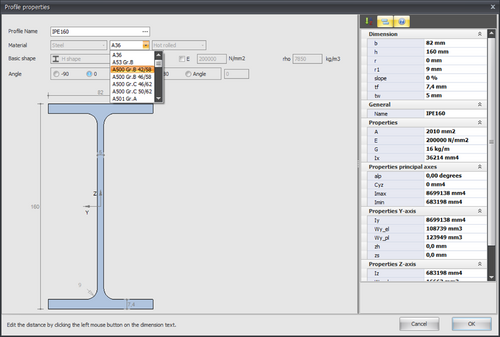
| Additional steel types are added.
· A36 · A53 Gr.B · A500 Gr.B 42/58 · A500 Gr.B 46/58 · A500 Gr.C 46/62 · A500 Gr.C 50/62 · A501 Gr.A · A501 Gr.B · A529 Gr.50 · A529 Gr.55 · A709 36 · A1043 36 · A1043 50 · A1085 Gr.A · A572 Gr. 42 · A572 Gr. 50 · A572 Gr. 55 · A572 Gr. 60 · A572 Gr. 65 · A618 Gr.la.lb · A618 Gr. III · A709 50 · A709 50S · A709 50W · A913 50 · A913 60 · A913 65 · A913 70 · A992 · A1065 Gr.50 |
 | |
| XFrame2D,XBeam2D
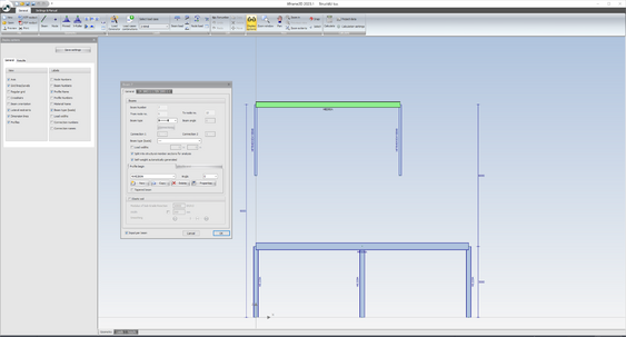
On the geometry tab, profiles can now be displayed. There is a new display option "Profiles" |
| |
| Improvement of the implementation of the NEN-EN 1993
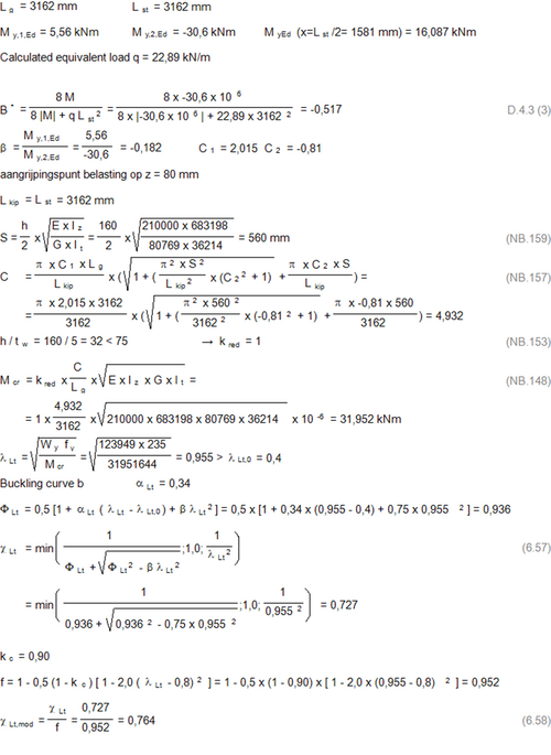
Lateral buckling stability: I-shaped sections were tested according to formula (6.56) of article 6.3.2.2. This is a conservative and therefore safe calculation. However, for I-sections it is also possible to use formulae (6.57) and (6.58) of article 6.3.2.3. Generally this leads to lower / more favorable unity checks. And we have now provided that. This can further optimize the design of your steel structure and save steel weight. |
 | |
| Material properties are included in the calculation output. |  | |
| 3D Wind load generator Eurocode. Several improvements with specific roof types. | 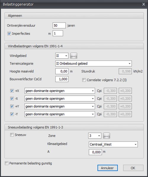 | |
| Every product of the Struct4U Engineering Tools has a startup splash screen. | 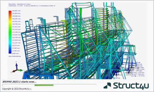 | |
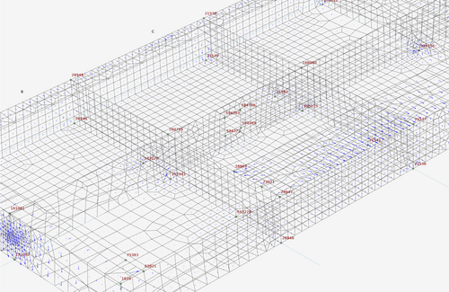
| Mesher. Several improvements have been made within the mesher. Especially with big structures.
Calculations of large structures is improved up to 300%. |
 |
General News
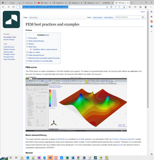
| The Struct4U Knowledge Center is online! https://wiki.struct4u.com
Although it is still under construction there is already a lot of information, documentation, tutorials and best practices about the software of Struct4U. |
 |
| Partner in Latin America: Roca Digital Sales.
Since this year Roca Digital Sales is the sales representative of Struct4U in Latin America. |
 |
| New website and logo! | 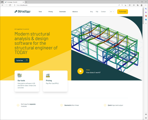 |
| Student version. Students all over the world can use Struct4U software for free!
For more information have a look at this page. |
 |
| Payment methods. Several new payment methods have been added. | 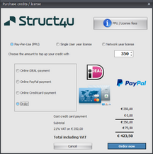 |
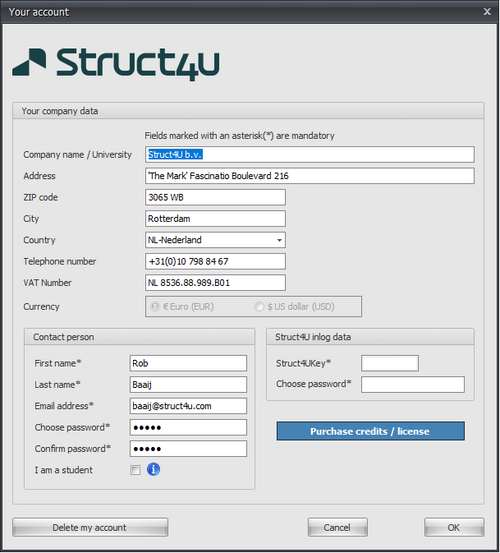
| Dollars/Euro’s. The analysis credit is now split in dollar and euro.
If you are in a dollar area you can buy your credit in dollars without exchange rate losses. |
 |
| Struct4U YouTube channel. Our YouTube channel has a new playlist: Tutorial4U.
Within this playlist we are working to add dozens of YouTube videos with tutorials and instructions. |
 |
| An additional license type is introduced: Network License.
All the licenses can be purchased via the Software. For more information have a look at this page. |
Sneak Preview
Sneak preview about coming features
The Struct4U development team is currently working on a couple of big improvements within the software.
- Non-Lineair analysis of concrete plates based on the actual reinforcement in the plate.
- Mobile loads.
- New XConstruct modules.
