XBeam2D Loads: Difference between revisions
No edit summary |
No edit summary |
||
| Line 132: | Line 132: | ||
===Beam Loads=== | ===Beam Loads=== | ||
Beam loads are inserted in a local beam coordinate system. See Design arrangement. | Beam loads are inserted in a local beam coordinate system. See [[Design arrangement. | http://68.183.11.126/index.php/Struct4U_Design_Arrangements]] | ||
[[File:XBeam2DBeamLoads1.png|frameless]] | [[File:XBeam2DBeamLoads1.png|frameless]] | ||
| Line 148: | Line 148: | ||
Choose the type of load you want to add. | Choose the type of load you want to add. | ||
{| class="wikitable" | {| class="wikitable" | ||
|- | |- | ||
!Type!!Description | |||
|- | |- | ||
| | |[[File:load-q.png|20 px|Wikipedia encyclopedia|link=http://68.183.11.126/index.php/File:Load-q.png]]||Even distributed load, or varying load | ||
| | |||
|- | |- | ||
| | |[[File:Load-F.png|20 px|Wikipedia encyclopedia|link=http://68.183.11.126/index.php/File:Load-F.png]]||Point force - F-load | ||
| | |- | ||
|} | |[[File:Load-M.png|20 px|Wikipedia encyclopedia|link=http://68.183.11.126/index.php/File:Load-M.png]]||Moment - M-load | ||
'''q1''' | |}'''q1''' | ||
The magnitude of the load. For the q-load the magnitude of the load at the beginning in kN/m. For a point load the amplitude of the load in kN. For a moment the magnitude of the load in kNm. | The magnitude of the load. For the q-load the magnitude of the load at the beginning in kN/m. For a point load the amplitude of the load in kN. For a moment the magnitude of the load in kNm. | ||
With plus min you can change the sign of the loads very easy. Standard the sign is at | With plus min you can change the sign of the loads very easy. Standard the sign is at min because this is most common. | ||
'''q2''' | '''q2''' | ||
Only for the q-load the magnitude of the load at the end in kN/m. | Only for the q-load the magnitude of the load at the end in kN/m. | ||
'''a''' | '''a''' | ||
The distance in mm where the load starts, counted from the begin node of the beam. | The distance in mm where the load starts, counted from the begin node of the beam. | ||
'''L''' | '''L''' | ||
Only for the q-load the length of the load should be inserted. Standard the load is going up to the end of the beam. | Only for the q-load the length of the load should be inserted. Standard the load is going up to the end of the beam. | ||
'''Angle''' | '''Angle''' | ||
Only for the q- and F-load. The angle in degrees to the perpendicular. The direction opposite to the clockwise direction is positive. | Only for the q- and F-load. The angle in degrees to the perpendicular. The direction opposite to the clockwise direction is positive. | ||
'''Beam angle''' | '''Beam angle''' | ||
| Line 193: | Line 186: | ||
[[File:XBeam2DBeamLoads4.png]] | [[File:XBeam2DBeamLoads4.png]] | ||
You can take over the angle from the previous section. | You can take over the angle from the previous section. | ||
'''z''' | '''z''' | ||
| Line 199: | Line 193: | ||
This distance is only relevant for lateral-torsional buckling resistance check . | This distance is only relevant for lateral-torsional buckling resistance check . | ||
'''Table''' | '''Table''' | ||
| Line 204: | Line 199: | ||
Beam loads can also be added/changed in the table. It does not matter. It is also possible to change in between graphical input and numerical input via tables. | Beam loads can also be added/changed in the table. It does not matter. It is also possible to change in between graphical input and numerical input via tables. | ||
[[File:XBeam2DBeamLoads5.png|none|frame]] | [[File:XBeam2DBeamLoads5.png|none|frame]] | ||
===Node === | |||
Revision as of 18:46, 5 September 2022
Loads
Every load (node load, beam load or node displacements) are inserted per load case.
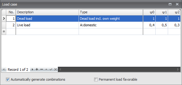
Load cases
Beam load
Node load
Node displacement
Input of the load cases
No.
This number is generated automatically. You can not change this number
Description
Free text to describe the load case
Type
The type of load. Dependent on the type of load, standard combination factors psi0, psi1, and psi2 are determined according to the Eurocode.
These combination factors are offered as a standard by entering the load combinations. However, these values can be adapted.
Automatically two load combinations are generated. Permanent and variable loads.
Automatically generate combinations
When you enter/change load combinations, the load combinations are automatically generated. You can also change these combinations and expand them.
Sequence load cases
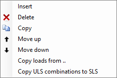
With a click on the right mouse button, the context menu shown below is opened. With these functions you can easily adapt the sequence of the load cases and/or insert load cases.
Insert
A new load case is created, and inserted above the current load case.
Delete
The load case is deleted, including all the loads
Copy
The load case is copied, including all the loads
Move up/ move down
A load can be moved up and down a line.
Copy loads from..
Every load from an already existing load case can be copied. The dialog box shown below is opened. Herein you choose the load case from which you want to copy the loads.
Load combinations
No.
This number is automatically generated. You can not change this number.
Description
Free text space to describe the load combination
Type
The type of load (ULS - ultimate limit state, ULS- fire, SLS-serviceability limit state, quasi permanent). Dependent on the type of combination, standard values for the combination factors (psi) and the load factor (gamma) are offered according to the Eurocode. But these values can be adapted.
Columns with load cases
For all the load cases, columns are created. In that way, a table appears in which all the combinations are shown. Every cell contains 2 values in the syntax : combination factor x load factor.
When you click on the cell the following dialog box appears. Here you can adapt both values.
For the combination factor and the load factor combo-boxes are offered including the standard values from which you can choose. You can also insert an own value. This gives a lot of freedom. If you for instance take one of the values as zero, the product of the two values obviously is zero as well. In that case the cell is showed 'empty'. This is only to make things clear.
Standard there are three load combinations generated. (ULS (6.10a), ULS (6.10b) and SLS)
Sequence load combinations
With a click on the right mouse button, the context menu shown below is opened. With these functions you can easily adapt the sequence of the load cases and/or insert load cases.
Insert
A new load combination is created and inserted above the current load case.
Delete
The load combination is deleted.
Copy
The load combination is copied.
Move up/ move down
A load combination can be moved up and down a line.
Copy ULS combination to SLS
Every load combination of the type ULS will be copied as type SLS. The load factors are set to 1.
Beam Loads
Beam loads are inserted in a local beam coordinate system. See http://68.183.11.126/index.php/Struct4U_Design_Arrangements
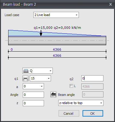
The dialog box shown below is opened.
Load case
Choice for the load case. Here you can directly insert a new load case.
Type of load
Choose the type of load you want to add.
| Type | Description |
|---|---|
| Even distributed load, or varying load | |
| Point force - F-load | |
| Moment - M-load |
q1
The magnitude of the load. For the q-load the magnitude of the load at the beginning in kN/m. For a point load the amplitude of the load in kN. For a moment the magnitude of the load in kNm.
With plus min you can change the sign of the loads very easy. Standard the sign is at min because this is most common.
q2
Only for the q-load the magnitude of the load at the end in kN/m.
a
The distance in mm where the load starts, counted from the begin node of the beam.
L
Only for the q-load the length of the load should be inserted. Standard the load is going up to the end of the beam.
Angle
Only for the q- and F-load. The angle in degrees to the perpendicular. The direction opposite to the clockwise direction is positive.
Beam angle
The angle in degrees with the global x-axis. The direction opposite to the clockwise direction is positive. With
![]() You can take over the angle from the previous section.
You can take over the angle from the previous section.
z
The distance in the z-direction in mm relative to the reference line. The reference line is adjustable. 'z relative to top', 'z relative to centerline', 'z relative to bottom'.
This distance is only relevant for lateral-torsional buckling resistance check .
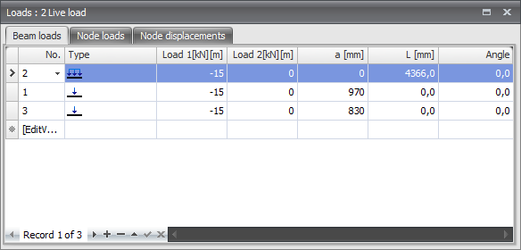
Table
Beam loads can also be added/changed in the table. It does not matter. It is also possible to change in between graphical input and numerical input via tables.


