Documentation XFEM4U
Introduction
This page contains the documentation of XFEM4U. It is meant as a full description of all functions and possibilities of the program. Other relevant information about XFEM4U can be found in the following links:
Release Notes
Releasenotes of XFEM4U: [link]
Possibilities and limitations
Full list of features of XFEM4U can be found here.
Coordinate System
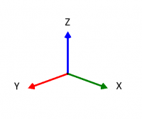
The program knows four clockwise coordinate systems.
Main coordinate system
The location of this global coordinate system is arbitrary. The XY-plane coincides with the plane of the framework. This coordinate system is used for setting the node coordinates, node limitations and node loads. Calculated node deformations and support reactions will be displayed relative to this coordinate system.

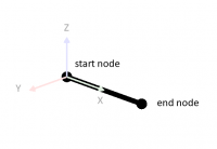
Beam coordinate system
The origin of this coordinate system is always in the beginning of the relevant beam. The XZ-plane coincides with the plane of the framework. The x-axis coincides with the beam-axis.

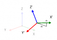
Node coordinate system

It is possible to use a local (node-) coordinate system. The origin lies in the relevant node. The direction of the x-axis is determined by assigning a relative dx and dz coming from the relevant node ( see the figure above). Local coordinate systems can be used to calculate node limitations ( support reactions and restrains ), node loads and/or node deformations in an arbitrary direction.
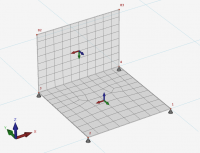
Plate coordinate system
The planar plane of the plate is the local XY-plane. If the plate is drawn clockwise then the Z-axe is positive.

The in- and output data will be displayed with regard to the above explained coordinate system.
- A force in the direction of the positive x- or z- axis is considered positive.
- A moment rotating from the positive x-axis to the positive z-axis (according to the cork-screw rule) is positive.
- A moment opposite to the 'clockwise' rotation is positive.