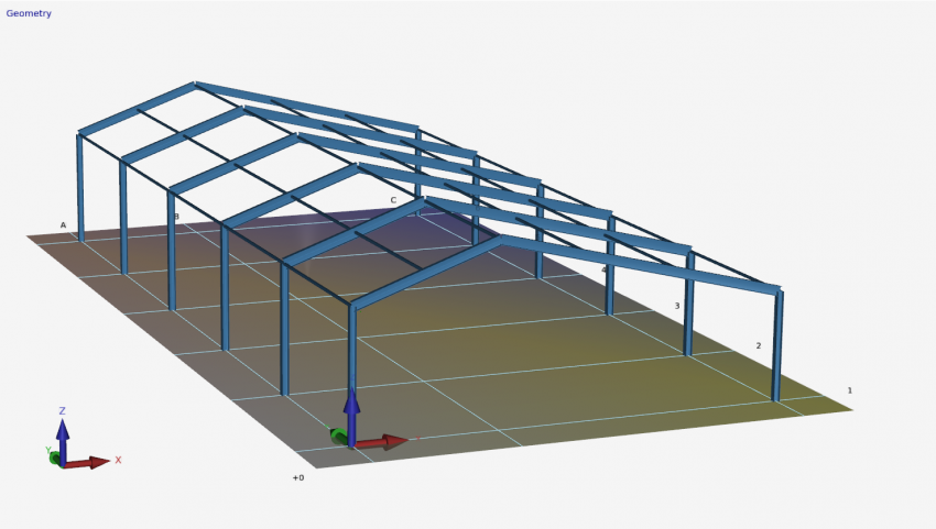
Documentation XFEM4U
Introduction
This page contains the documentation of XFEM4U. It is meant as a full description of all functions and possibilities of the program. Other relevant information about XFEM4U can be found in the following links:
Release Notes
Releasenotes of XFEM4U: [link]
Possibilities and limitations
Full list of features of XFEM4U can be found here.
Coordinate System
The program knows four clockwise coordinate systems.
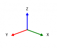
Main coordinate system
The location of this global coordinate system is arbitrary. The XY-plane coincides with the plane of the framework. This coordinate system is used for setting the node coordinates, node limitations and node loads. Calculated node deformations and support reactions will be displayed relative to this coordinate system.
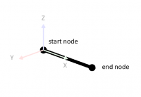
Beam coordinate system
The origin of this coordinate system is always in the beginning of the relevant beam. The XZ-plane coincides with the plane of the framework. The x-axis coincides with the beam-axis.
Node coordinate system
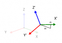
It is possible to use a local (node-) coordinate system. The origin lies in the relevant node. The direction of the x-axis is determined by assigning a relative dx and dz coming from the relevant node ( see the figure above). Local coordinate systems can be used to calculate node limitations ( support reactions and restrains ), node loads and/or node deformations in an arbitrary direction.
Plate coordinate system
The planar plane of the plate is the local XY-plane. If the plate is drawn clockwise then the Z-axe is positive.
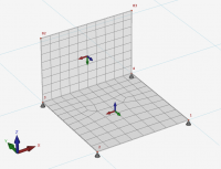
The in- and output data will be displayed with regard to the above explained coordinate system.
- A force in the direction of the positive x- or z- axis is considered positive.
- A moment rotating from the positive x-axis to the positive z-axis (according to the cork-screw rule) is positive.
- A moment opposite to the 'clockwise' rotation is positive.
Input
For navigating in your 3d model, 2 common methods are supported. You can set which one you want to use. Tab Settings & Manual > Settings > Navigate tab See Navigating
1. Method as in Autodesk Revit (default)
- 'Zooming in and out: Use the mouse wheel.
- 'Pan: Press the mouse wheel and drag.
- Orbit: Press the mouse wheel and SHIFT' key together and drag.
2. Method as in Tekla structures
- Zoom in and out": Use the mouse wheel.
- Pan": Press the mouse wheel and drag.
- Orbit": Press the mouse wheel and CTRL key together and drag.
XFEM4U also supports the use of a 3d mouse (from e.g. 3D Connection ) which makes working even easier and faster.
Geometry
In this section we have a look at all the geometry functions within XFEM4U
Beams
Preface
In the graphical screen beams can be added very easy by drawing them. Select this item in the function bar. Beams are drawn as a 'polyline' just as you know it from AutoCAD.The begin node from a following beam is the end node of the last drawn beam.
It is possible, but not necessary, to draw nodes before you insert the beams. You can also start with drawing the beams, in this way the nodes will be inserted automatically.
When you draw your first beam, the dialog box shown below appears. In this box you can, among other things, insert the beam connections and the profile of the beam. Use the escape-key or click the right mouse button to end the drawing of the beams.
As you are drawing a beam, help lines (horizontal and vertical) will appear connected to the previous inserted nodes. Often the node, to which you want to draw the beam, has the same x- or y- or z-value as the previous one. In this way it is easy to insert nodes. Obviously you can adapt the coordinates afterwards numerically or by moving the node.
While drawing a new beam, a dimension line parallel to the beam in one of the main directions x,y or z will appear. You can, just as you know it from AutoCad, immediately insert the distances numerically by entering the value / values from your keyboard. There are 3 possibilities for drawing a beam:
1. Drawing a beam with a known length in one of the main directions.
The value will appear in the dimension line. Here you can type in the distance. By the use of the enter-key the input is closed and the beam with that length will be added.
2. Drawing a beam using relative Cartesian coordinates (dx, dy, dz).
First you enter the distance in x-direction. The value will appear in the dimension line. Thereafter you type a semicolon ";" and the distance in y-direction. The value will appear in a second input field. Next you type a semicolon ";" and the distance in z-direction. The value will appear in a third input field. By the use of the enter-key the input is closed and the beam is added.
3. Input of relative cartesian coordinates (dx, dy, dz) or absolute cartesian coordinates (x, y, z).
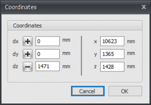
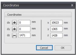
Press the space key and the dialog box below appears. Here you can enter relative coordinates or absolute coordinates directly.
In this way, you can quickly insert your construction.
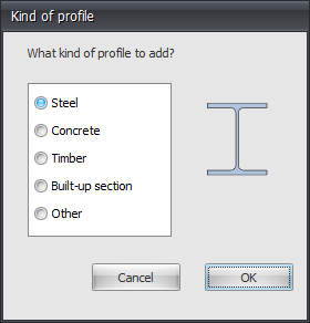
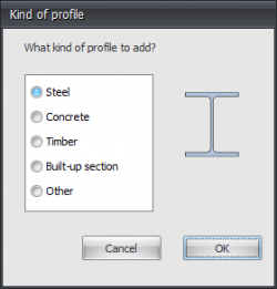
When you draw a beam for the first time, a profile needs to be chosen / inserted. There is asked what kind of profile you want to add. Also when you insert a new profile, there is asked which kind of profile you want to add.
Subsequently the following dialog box of the profiles is shown. See Profiles
Changing a beam
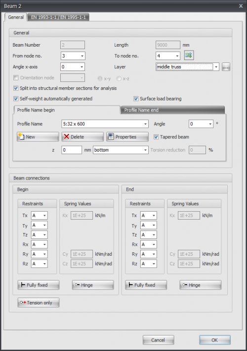
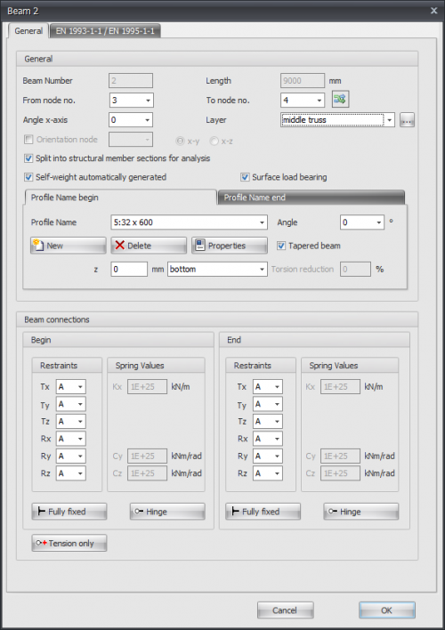
Changing a beam is possible by clicking on the beam with the left mouse button, and subsequently choose for properties by clicking with the right mouse button. There is a more easy way, namely a double click on the beam. Consequently the following dialog box will be opened.
Beamproperties: General
Beam number
The number of the beam.
Length
The length of the beam in mm.
From node no.
The number of the begin node.
To node no.
The number of the end node.
flip
By the use of this function, you can turn around the beam orientation. The begin- and end node will be switched.
Angle x-axis
The angle in which the local coordinate system can rotate around the x-axis.
The clockwise direction is positive.
Layer
Beams can optionally be drawn in layers. This corresponds to the functionality of AutoCAD. The layers can be set visible or invisible. (on/off). You can adapt the names of the layers. See Display options
Orientation node
The number of the orientation node. This is a node in the local x-y plane or in the x-z plane.
Split into structural member sections for analysis
Setting whether, for the determination of the force distribution (framework calculation), the beam has to be split in in partial beams when nodes are found on the beam. This function is enabled by default.
Self-weight automatically generated.
Setting whether the dead weight of the beam needs to be generated. This function is enabled by default. See Calculation settings
Surface load bearing
Setting whether the beam carries the surface load or not. See Surface loads
Profile Name
Here you choose the profile type
Angle
The angle of the profile. That is the angle relative to the local coordinate system. Normally this is zero degrees. When you want to for example enter the column rotated (so loaded at it's weak axis) you fill in 90 degrees
New Delete Properties
You can also add new profiles and delete profiles. Choose for Properties when you want to adapt the profile data and/or want to select another standard profile type from the profile database.
With every new profile, there is asked what kind of profile you want to add.
Tapered beam
You can optionally enter a tapered beam (Non-prismatic beam). The tab "Profile end" is activated. Here you can enter the 2nd profile at the end of the beam. Attention! The basic shape of the profile section (H-, U-, L-shape, etc.) must match that of the profile at the beginning of the beam.
For calculation background. See Tapered beam
z
With this the profile is orientated relative to the schematic line. ( The schematic line is the line from the begin node to the end node) z is the distance in the local z-direction between the schematic line and the reference line of the profile. The reference line of the profile is showed in the middle by default, but can be set at the top, middle or bottom.
Torsion reduction
Percentage by which the torsion stiffness of the beam is reduced. Specifically for concrete beam grids, it is allowed to reduce the torsion stiffness in case of compatibility torsion. Thereby the occurring torsion moment is lower, and less torsion reinforcement is needed. (stirrups and longitudinal reinforcement)
Beam connection begin and end
Here you enter how the beam is connected at the begin node and at the end node. There are multiple options.
You can make use of the most common / standard connections:
Fully fixed
Tx=A(Absolute), Ty=A, Tz=A, Rx=A, Ry=A, Rz=A. (That is the standard setting)
Hinge
Tx=A, Ty=A, Tz=A. There is no transfer possible between moments, only shear force and normal force.
Tension only
This works the same as a hinge support, the only difference is that tensile forces (positive normal forces) can be transferred.
Springer connection
You can also add a beam with a springer connection. Tx=S(Spring), Ry=S en/of Rz=S. You also need to insert the spring constant Kx, Cy and/or Cz in kN/m resp. kNm/rad
Input per beam
This gives you the possibility to adapt the input for every new beam.
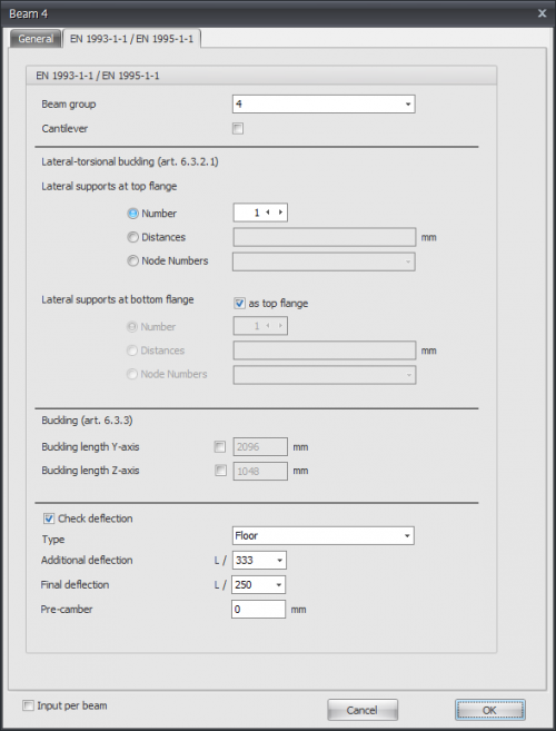
Beamproperties: Eurocode
EN 1993-1-1 / EN 1995-1-1
Specifically and only for the check according to Eurocode 3: EN 1993-1-1 respectively Eurocode 5: NEN-EN 1995-1-1data can be inserted.
Beam group
Specifically and only for the lateral-torsional buckling resistance check a beam group can be inserted here. XFEM4U automatically detects for which beams this qualifies. Only the beams which are connected by a fully fixed connection to this particular beam and have the same profile will be showed. You can select which beams should be taken into account. For this group you subsequently enter the length between the lateral restraints and the buckling length out of plane.
Lateral torsional buckling
Amount of lateral supports / distances between lateral supports
This is only relevant for the check of lateral torsional buckling. You can enter the lateral supports for the top and the bottom flange.
There are 3 options:
1. Number: The amount of lateral supports. That are the extra (lateral supports) between the supports distributed over the length of the beam(group)
2. Distances: The lengths between the lateral restraints from the beginning of the beam (group). The syntax is length1 length2 amountxlenght3.. etc.
For example 3000 3x2200 2800
3. Node numbers: Selecting the node numbers which are in the beam group.
Buckling lengths Y-axis and Z-axis
The check according to Eurocode 3: EN 1993-1-1 is based on a geometric non linear force distribution. This means that the buckling of the beams in the plane of the frameworks is provided implicit in the force distribution. For every load combination the internal stability is determined iteratively. By default the buckling length around the y-axis is equal to the beam length. The buckling length around the z-axis is equal to the biggest lateral torsional buckling length. You can also enter different values for both the buckling lengths. See also Buckling.
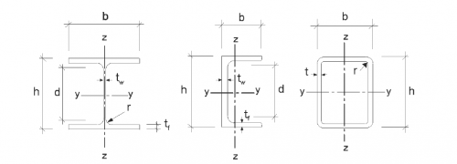
Note: Regardless of whether the profile is rotated with respect to the local coordinate system, the Y axis is the strong axis and the Z axis is the weak axis analogous to the Eurocode. (See below.) In all checks, all beam forces are transformed to this coordinate system.
Check deflection
Setting if deflection has to be checked.
Type
This influences the requirement of additional deflection.
Additional deflection
Requirement of additional deflection.
Final deflection
Requirements of final deflection.
Pre-camber
The size of pre-camber in mm.
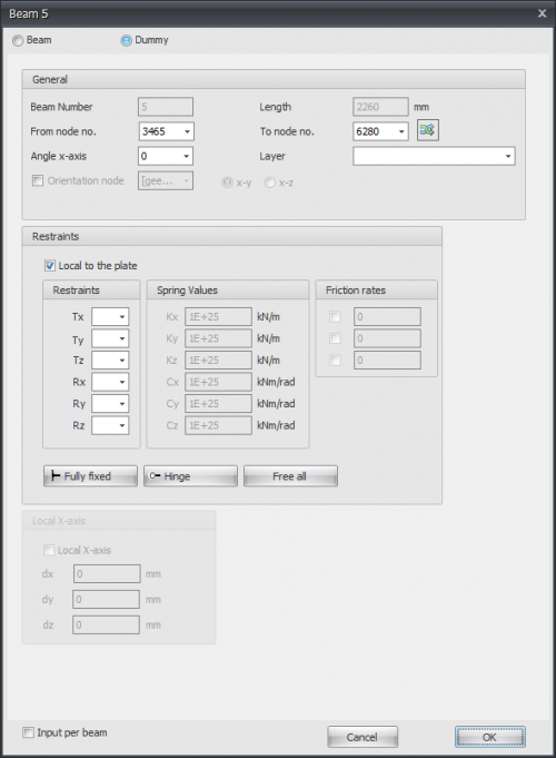
Beamproperties: Dummy
Specifically for plates, it is possible to enter dummy beams. Arithmetically, a dummy beam is taken into account with small bending stiffness.
Line Loads: With dummy beams, any line loads on a plate can be taken into account.
Line supports: Dummy beams can be supported by.
Beam number
The number of the beam.
Length
The length of the beam in mm.
From node no.
The number of the begin node.
To node no.
The number of the end node.
flip
By the use of this function, you can turn around the beam orientation. The begin- and end node will be switched.
Angle x-axis
The angle in which the local coordinate system can rotate around the x-axis.
The clockwise direction is positive.
Layer
Beams can optionally be drawn in layers. This corresponds to the functionality of AutoCAD. The layers can be set visible or invisible. (on/off). You can adapt the names of the layers. See Display options
Orientation node
The number of the orientation node. This is a node in the local x-y plane or in the x-z plane.
Line supports
Indication/ Description
' ' free - no limitation
'A' Fully limited (Absolute)
'P' Limited for a Positive reaction force; free for a negative reaction force
'N' Limited for a Negative reaction force; free for a positive reaction force
'S' Springer (Spring); spring value needs to be inserted
Local to the plate
Setting whether the supports are to be introduced in relation to the local axle system of the plate.
Supports / Restraints
Here you enter how the beam is supported. There are many possibilities.
You can use the most common / standard supports:
- Fully fixed Tx=A(Absolute), Ty=A, Tz=A, Rx=A, Ry=A, Rz=A. (That is the default setting)
- Hinged Tx=A, Ty=A, Tz=A. No moments can be transmitted, only transverse and normal forces.
Spring support
You can also enter a spring support. Tx=S(Spring), Ry=S and/or Rz=S. You also give the spring value Kx, Cy and/or Cz in kN/m or kNm/rad.
Local x-axis see Local coordinate system
Input per beam
This gives you the possibility to adapt the input for every new beam.
Profiles
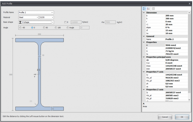
The first time you draw a beam, a profile needs to be chosen / inserted. There is asked what kind of profile you want to add. Also if you want to enter a new profile, there is asked what kind of profile you want to insert.
Steel
Remark:
You can adapt all profile dimensions by clicking on the concerning values in the dimension lines.
Profile name:
You can enter the profile name here, or select a profile from the database. You can also directly type IPE160, HEA200 or HE200A here.
Do you want to enter a common steel profile from the database, click on the 3 dots... at the right side of the input field.
After you selected a basic shape, you can subsequently adapt all the profile dimensions by clicking on the concerning numbers in the dimension line. You can also adapt the profile dimensions of the standard profiles by the use of this method.
E
The elasticity modulus, which is adaptable.
Angle
You can rotate the profile among an angle
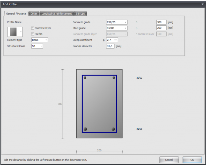
Concrete
Cross sectional shape
You can choose from a big amount of cross sectional shapes. When you chose a shape, you can subsequently adapt the profile dimensions by clicking on the concerning values in the dimension lines.
Concrete top layer
Setting whether you want to insert a in-situ concrete top layer with a different concrete grade
Prefab
Setting whether you want to use prefab concrete
Concrete grade
The concrete grade
Steel grade
The steel grade of the basic and additional reinforcement.
Creep coefficient
The creep coefficient of concrete. By this coefficient the effective creep coefficient is calculated according to EN 1992-1-1 art. 5.8.4.
You can insert the creep coefficient yourself or you can have it calculated. See Creep. When the creep coefficient is calculated, a detailed calculation according to EN 1992-1-1 B.1 is displayed in the output as well.
Granule diameter
The nominal granule diameter of concrete
Granule diameter
The nominal granule diameter of concrete
h
The height of the concrete cross section in mm
b
The width of the concrete cross section in mm
h concrete layer
The height of the in-situ concrete top layer in mm
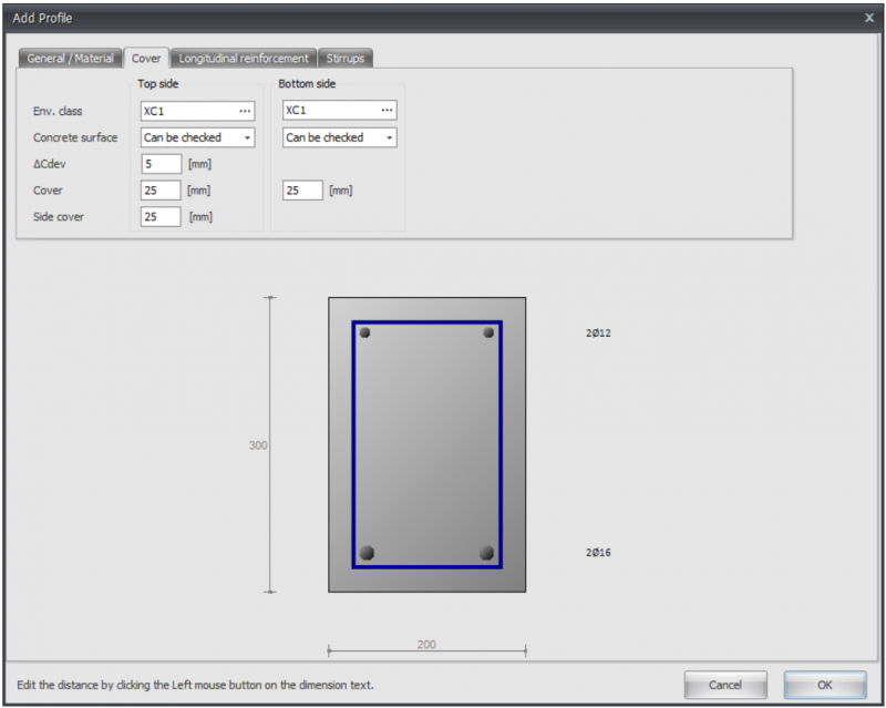
Environmental class
The environmental or exposure class is used for the determination of the required cover. See Exposure classes
Concrete surface
Can be checked, can not be checked or finished
delta_Cdev
Execution tolerance of the concrete cover in mm
Cover
Concrete cover top / bottom in mm
Side cover
Side cover left / right in mm
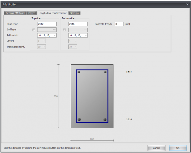
Basic reinforcement
Basic reinforcement top/bottom
Syntax 1: <amount>x<diameter> [+<amount>x<diameter>...]
Syntax 2: <diameter>-<ctc distance> [+<diameter>-<ctc distance>...]
Syntax 3: <mm2> [ / <diameter>]
2nd layer
Basic reinforcement top / bottom in the second layer
Additional reinforcement diameters
The diameters by which the additional reinforcement is designed
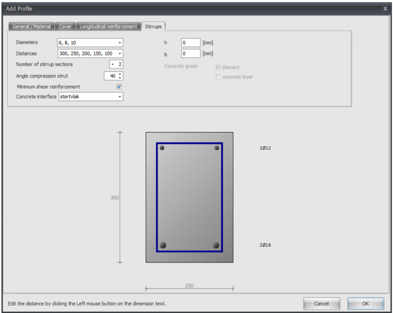
Layers
When designing a floor, the option if the basis reinforcement is in the first or in the second layer
Transverse reinforcement
When designing a floor, the diameter of the transverse reinforcement
Concrete trench
Concrete trench in mm
Diameters
Stirrup diameters
Distances
Stirrup distances
Number of stirrup sections
The number of stirrup sections. For shear force this is normally 2.
Angle compression strut
Angle compression strut in degrees
Minimum shear reinforcement
Setting whether the minimum shear reinforcement should be taken in to account.
Concrete interface
In the case of a in-situ concrete top layer, the pouring surface can be entered here.
h
Height of the concrete cross section for the shear force calculation in mm.
b
Width of the concrete cross section for the shear force calculation in mm.
Concrete grade
In case of a in-situ concrete top layer: Concrete grade that needs to be used for the shear force calculation.
Timber
Remark:
You can change the profile sizes by clicking on the concerning values in the dimension line.
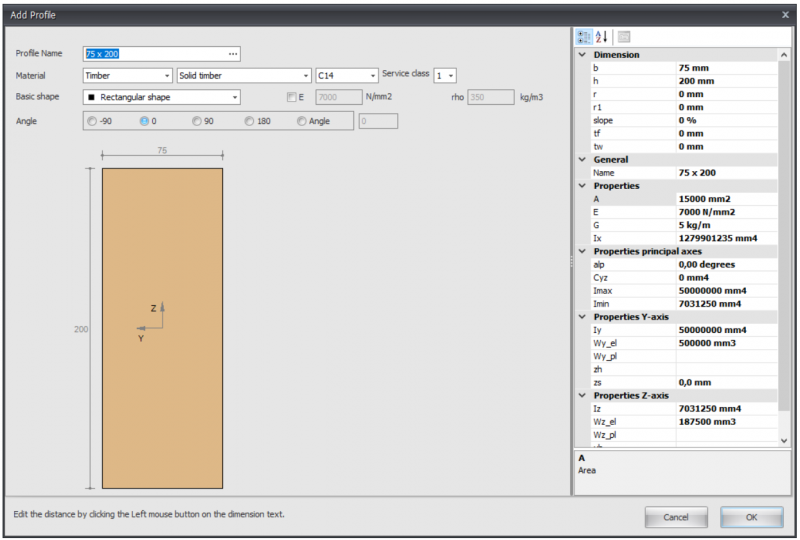
Profile name
Enter the profile name or select a profile from the existing database. You can also directly type 75 x 200 of 75 x 225
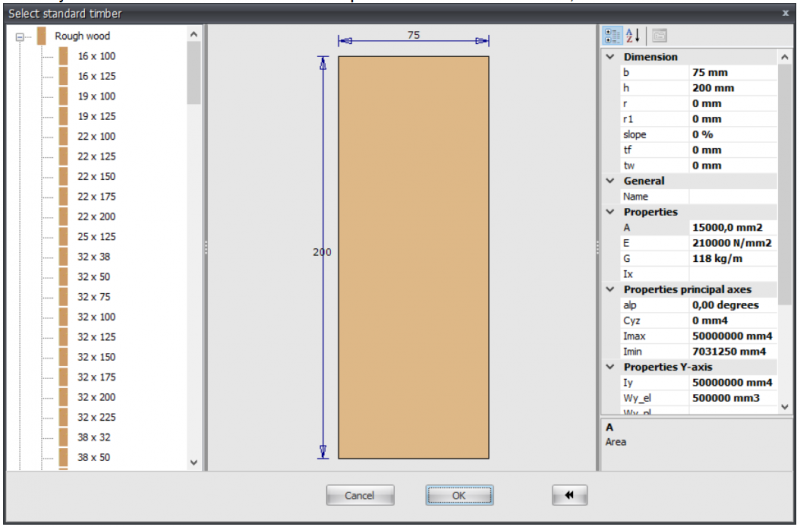
When you want to enter a known timber profile from the database, click on the 3 dots... on the right side of the input field.
Material
Timber
Type of timber
Timber class
Climate class
Basic shape
You can choose from an amount of basic shapes. In this way you can make the profile yourself.
After you selected a basic shape, you can subsequently adapt all the profile sizes by clicking on the concerning values in the dimension line. You can also can adapt the profile sizes of the standard profiles in this way.
E
The elasticity modulus which is adaptable
Angle
You can rotate the profile among an angle
Build-up selection
With this module you can built up any section.
Input
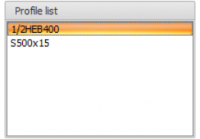
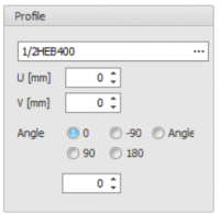
You can Add, Copy and Delete any profiles here. Using Properties you can change your profile or alter the profile dimensions.
Profile name
Enter the profile name or select from our profile database.
Special input:
- Half H syntax: "1/2 profile name [ - min dimension ]" Example: 1/2IPE300 or 1/2HE650B-5
- Rectangular: syntax: "S width x height" of "F width x height" Example: S200x12
- Hole: syntax: "G width x height" of "H width x height" Example: H50x2
- Round: syntax: "R diameter Example: R50
- Tube(segment): syntax: "R diameter x thickness [ / hoek1 / hoek2 ] " Example: R500x12 or R500x12/0/180
- Trangle: syntax: "D width x height" of "T width x height" Example: T50x60
U
Coordinate u in mm
V
Coordinate v in mm
Angle
Angle in degrees
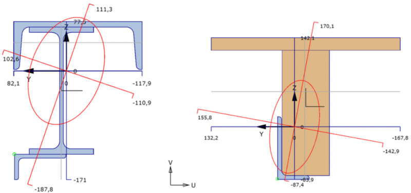
Graphical input
Graphical view of the built up section, with:
- cross section of all profiles use. The focused section is displayed with another color.
- coordinate system
- centroid
- principal axis
- distances from centroid to all largest dimension
- display of radius of gyration
- display of plastic neutral axis
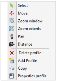
Mouse right click context menu
Menu
Slabs/Plates
General
In the graphical screen slabs can be added very easy by drawing them. Select this item in the function bar.
![]()
Plate egdes are drawn as a 'polyline' just as you know it from AutoCAD.The begin node from a following beam is the end node of the last drawn plate edge.
It is possible, but not necessary, to draw nodes before you insert the plates.
You can also start with drawing the plate edges, in this way the nodes will be inserted automatically.
When you draw your first plate edge, the dialog box shown below appears. In this box you can, among other things, insert the material data of the slab. Use the escape-key or click the right mouse button to end the drawing of the plate edges.
As you are drawing a plate edge, help lines (horizontal and vertical) will appear connected to the previous inserted nodes. Often the node, to which you want to draw the beam, has the same x- or y- or z-value as the previous one. In this way it is easy to insert nodes. Obviously you can adapt the coordinates afterwards numerically or by moving the node.
While drawing a new plate edge, a dimension line parallel to the plate edge in one of the main directions x,y or z will appear. You can, just as you know it from AutoCad, immediately insert the distances numerically by entering the value / values from your keyboard. There are 3 possibilities for drawing a plate edge:
1. Drawing a plate edge with a known length in one of the main directions.
The value will appear in the dimension line. Here you can type in the distance. By the use of the enter-key the input is closed and the plate edge with that length will be added.
2. Drawing a plate edge using relative Cartesian coordinates (dx, dy, dz).
First you enter the distance in x-direction. The value will appear in the dimension line. Thereafter you type a semicolon ";" and the distance in y-direction. The value will appear in a second input field. Next you type a semicolon ";" and the distance in z-direction. The value will appear in a third input field. By the use of the enter-key the input is closed and the plate edge is added.
3. Input of relative cartesian coordinates (dx, dy, dz) or absolute cartesian coordinates (x, y, z).
Press the space key and the dialog box below appears. Here you can enter relative coordinates or absolute coordinates directly.
In this way, you can quickly insert your slab/plate.
The plate can be supported in different ways. By Nodes and/or Plate edge.
You can enter Plate loads and/or Node loads.
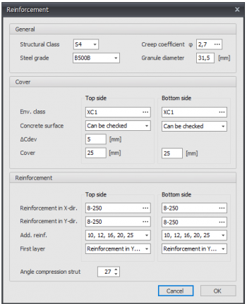
Reinforcement
General
Steel grade
The steel grade of the basic and additional reinforcement.
Creep coefficient
The creep coefficient of concrete. By this coefficient the effective creep coefficient is calculated according to EN 1992-1-1 art. 5.8.4.
You can insert the creep coefficient yourself or you can have it calculated. See Creep. When the creep coefficient is calculated, a detailed calculation according to EN 1992-1-1 B.1 is displayed in the output as well.
Granule diameter
The nominal granule diameter of concrete.
Cover
Environmental class
The environmental or exposure class is used for the determination of the required cover. See Exposure classes
Concrete surface
Can be checked, can not be checked or finished
delta_Cdev
Execution tolerance of the concrete cover in mm
Cover
Concrete cover top / bottom in mm
Reinforcement
Reinforcement in X- and Y-direction
Basic reinforcement top/bottom
Syntax 1: <amount>x<diameter> [+<amount>x<diameter>...]
Syntax 2: <diameter>-<ctc distance> [+<diameter>-<ctc distance>...]
Syntax 3: <mm2> [ / <diameter>]
Additional reinforcement diameters
The diameters by which the additional reinforcement is designed
Layers
Setting which reinforcement is in the first layer
Angle compression strut
Shear reinforcement: Angle compression strut in degrees
Holes in plate
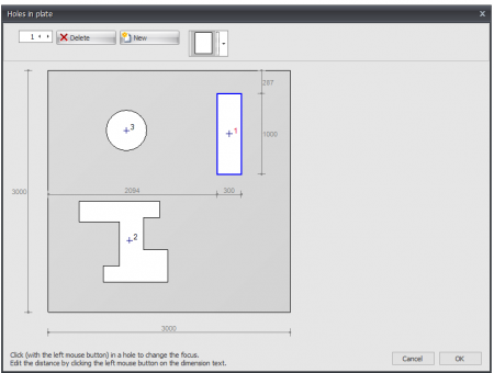
Here you can easily enter holes or openings. You can choose from a large number of basic shapes that are parameterized.

The position and dimensions of the hole or opening can be adjusted by clicking on the relevant dimension line. The focus in case of multiple holes can be changed by clicking with the left mouse button in the hole contour. If you hold down the left mouse button and move the mouse, you can move the hole graphically. It checks whether holes overlap or cut through the outer contour.
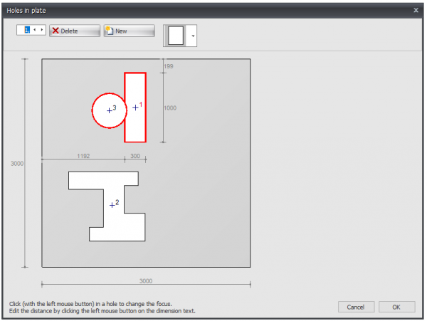
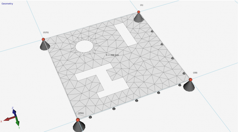
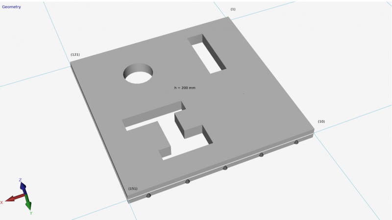
Plate edge
Plate edges are drawn as transparent tubes. By double-clicking on a plate edge (or 1 click right mouse button > Properties) the dialog box below becomes visible.
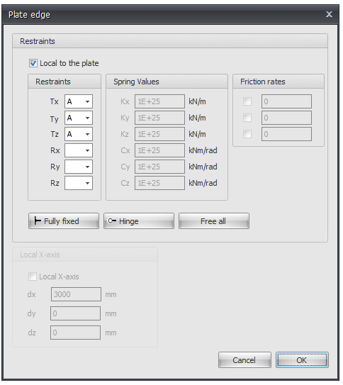
Local to the plate
Setting whether the supports are to be introduced in relation to the local axle system of the plate.
Supports / Restraints
Here you enter how the plate edge is supported. There are many possibilities.
You can use the most common / standard supports:
Fully fixed Tx=A(Absolute), Ty=A, Tz=A, Rx=A, Ry=A, Rz=A. (That is the default setting)
Hinged Tx=A, Ty=A, Tz=A. No moments can be transmitted, only transverse and normal forces.
Spring support
You can also enter a spring support. Tx=S(Spring), Ry=S and/or Rz=S. You also give the spring value Kx, Cy and/or Cz in kN/m or kNm/rad.
Local x-axis see Local coordinate system
Nodes
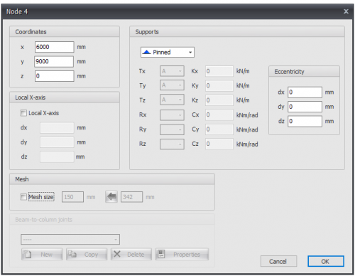
Nodes can easily be added in the graphical screen. To do this, you have to choose ![]() in the menu bar. In these modus you can add multiple nodes by means of the left mouse button. By placing the node, you will see the coordinates in the right bottom. As is shown in this image below.
in the menu bar. In these modus you can add multiple nodes by means of the left mouse button. By placing the node, you will see the coordinates in the right bottom. As is shown in this image below.
Nodes can be added arbitrary in a fixed raster or at grid lines.
Supports are nodes which are restrained in a certain direction.
Changing a node
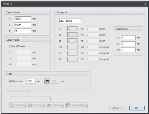
Changing a node is possible by clicking on the node by use of the left mouse button, and subsequently choose for properties by clicking on the right button. There is a more easy way, namely a double click on the node. Consequently the following dialog box will be opened.
Coordinates
x
x-coordinate
y
y-coordinate
z
z-coordinate
Local x-axis see Local coordinate system
Supports see Supports
These are the supports that are the most common in practice, but you can also add an arbitrary (spring) support by making use of the 'A', 'P', 'N' or 'S'.
Eccentricities
Only for supports ( nodes with restrictions / restraints in a certain direction) you can add a eccentricity by inserting 3 relative coordinates dx, dy and dz. An extra node and a 'stiff' beam are automatically generated. Hereby you can, for example, in the calculation of a concrete beam grid, take the misplacement of a pile into account. The foundation beams can subsequently be tested for torsion and extra bending.
Mesh see Mesh
Beam-to-column joints see Node joints
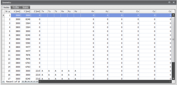
Table nodes
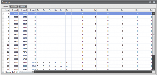
Nodes can also be added / changed in the bottom left table Nodes. It does not matter. It is also possible to change in between graphical input and numerical input via tables.
Local coordinate system
In every node a local node-coordinate system can be added.
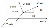
Example of a roller support among an angle.
Local X-axis
The origin lies in the relevant node. The direction of the x-axis is determined by 3 relative coordinates (see the figure above). Local coordinate systems can also be used to insert node limitations (supports or restraints), but also node loads and/or node displacements in an arbitrary direction.
Supports
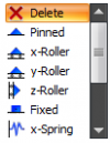
Standard supports can very easily be added in the graphical screen. In the menu bar you can choose for one of the following supports:
Remark:
These are the supports that are the most common in practice, but you can also add an arbitrary (spring) support by making use of the 'A','P','N' of 'S'. See the table below.
![]() Pinned support (Tz,Ty,Rz) ( 'A','A',' ')
Pinned support (Tz,Ty,Rz) ( 'A','A',' ')
![]() Roller support z-direction (Tx,Tz,Ry) ( ' ','A', ' ')
Roller support z-direction (Tx,Tz,Ry) ( ' ','A', ' ')
![]() Roller support x-direction (Tx,Tz,Ry) ( 'A',' ', ' ')
Roller support x-direction (Tx,Tz,Ry) ( 'A',' ', ' ')
![]() Fixed support (Tx,Tz,Ry) ( 'A','A', 'A')
Fixed support (Tx,Tz,Ry) ( 'A','A', 'A')
![]() Springer support x-direction (Tx,Tz,Ry) ( 'S',' ', ' ')
Springer support x-direction (Tx,Tz,Ry) ( 'S',' ', ' ')
![]() Springer support z-direction (Tx,Tz,Ry) ( ' ','S', ' ')
Springer support z-direction (Tx,Tz,Ry) ( ' ','S', ' ')
![]() Springer support y-direction (Tx,Tz,Ry) ( ' ',' ', 'S')
Springer support y-direction (Tx,Tz,Ry) ( ' ',' ', 'S')
Supports can be added arbitrary, in a fixed raster or on grid lines.
Supports are nodes which are restrained in a certain direction.
Changing a support
Changing a support is possible by clicking on the node by use of the left mouse button, and subsequently choose for properties by clicking on the right mouse button. There also is a more easy way, namely by a double click on the node or support. Consequently the following dialog box will be opened
| Indication | Description |
|---|---|
| ' ' | free - no limitation |
| 'A' | Fully limited (Absolute) |
| 'P' | Limited for a Positive reaction force; free for a negative reaction force |
| 'N' | Limited for a Negative reaction force; free for a positive reaction force |
| 'S' | Springer (Spring); spring value needs to be inserted |
Table Nodes
Supports can also be added/changed in the table nodes in the left bottom. It does not matter. It is also possible to change in between graphical input and numerical input via tables.
Mesh
Mesh size
The dimension of plate elements. The standard (recommended) mesh size is automatically determined but can be adjusted for each node.
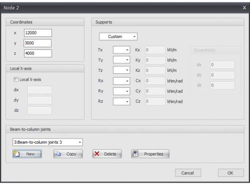
Node joints
You can add a new connection per node. When you have added the connection you can also apply the same connection in other nodes.
You can create / add new connections, copy and delete connections. Choose Properties when you want to change the connection.
See Joints
Joints
Joints can be entered at nodes.
Input in drawing
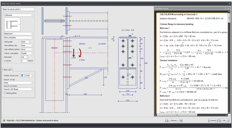
In the drawing of the connection you can change almost everything. You can change all sizes by clicking on the number in the dimension line. See Changing dimensions.
You can also change the profiles, beam angles and loads in the drawing. This not only works quickly, but is also intuitive. You will experience how easy and how pleasant it is to work with XFEM4U. The calculation results can be displayed on the right as "docked" or as a separate screen on a second monitor. With every change that is made, the calculation is carried out and the results are immediately visible. In that way you can quickly see the effect of your change. You can see everything in one overview, both the input and the calculation output.
Lb=4000
Length of the beam (This value can be changed in the drawing.)
The length is only important for the classification of the rotational rigidity of the connection. (rigid / semi-rigid / hinged)
0 <
Angle of the beam.
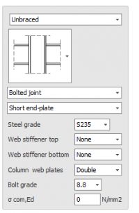
You set a number of parameters in the dialog box below.
Classification construction: Braced / Unbraced
This is only important for the classification of the rotational rigidity of the connection. (rigid / semi-rigid / hinged)
Type connection: Bolted joint / Welded joint
Type end plate: Short end-plate / Extended en-plate
Steel grade
Web stiffener top: None / Full / Partial
Web stiffener bottom: None / Full / Partial
Column web plates: None / Single / Double
Bolt grade
Sigma;com,Ed
The largest axial compression stress in the column. This is calculated automatically and does not need to be entered.
Beams symmetrical
With a double connection (left and right) you can set whether both are equal (symmetrical) or not. This means that when you change one side, the other side changes automatically
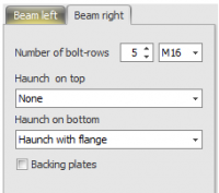
Number of bot-rows
The number of bolt rows is at least 2.
Bolt
Haunch on top: None / Haunch without flange / Haunch with flange
Haunch on bottom: None / Haunch without flange / Haunch with flange
Backing plates
Setting whether backing plates are used.
Grid lines/levels
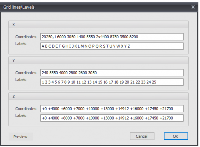
In XFEM4U it is possible to use a standard grid with grid lines. A standard raster is created, but you can adapt this raster.
Beams and nodes can be easily drawn into the grid. XFEM4U has a magnet function, which snaps to points into the grid.
Coordinates
You can define the grid lines yourself.
Syntax: distance spacing1 amount x spacing.. etc
Example: "0 3000 3x2200 2800".
For the z - coordinate, if you enter the numbers with a +, then you are entering absolute values.
Labels
The indication of the grid lines
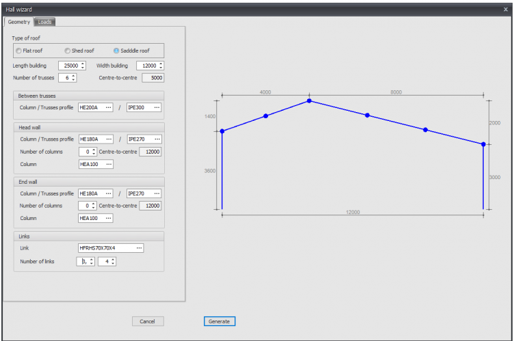
Wizard
By the use of wizard, you can quickly and easily generate the geometry and wind loads of a simple hall.
Internal hinge in a beam
Adding an internal hinge in the graphical screen is very easy.
Choose for the following image in the menu bar.cur_InternalHinge. ![]()
In these modus you can add multiple internal hinges by use of the left mouse button. By placing the hinge, the coordinates are shown in the right bottom.
When you add an internal hinge, a new node in the beam is generated, and the regarding beam is automatically divided into two beams with a hinge connection. The beam loads also will be adjusted automatically.
In this way you can easily design a gerber beam.


