|
|
| (4 intermediate revisions by the same user not shown) |
| Line 1: |
Line 1: |
| [[Documentation XFEM4U | BACK]] | | [[Documentation XFEM4U | BACK]] |
|
| |
|
| ====Edit====
| |
|
| |
|
| [[File:Edit.png|1200 px|Wikipedia encyclopedia]] | | [[File:Notifications.png | 30px]] Notifications |
|
| |
|
| =====Menu=====
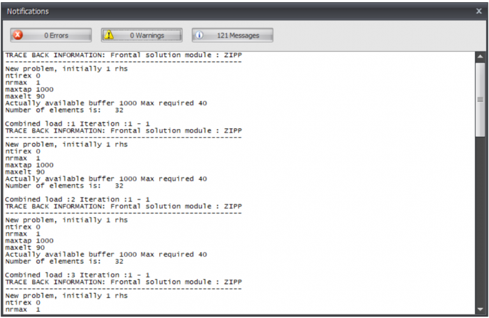
| | When the force distribution can not be calculated, for instance when the structure is instable, a dialog box is opened. This dialog can be reopened with the button shown above. In this dialog box the notifications of the calculation module are shown. |
|
| |
|
| [[File:Renumber 32x32.png|30 px|Wikipedia encyclopedia]] | | [[File:Notifications2.png | 700px]] |
|
| |
|
| '''Renumber'''
| |
|
| |
|
| With these function the nodes and beams will be renumbered
| |
|
| |
|
| [[File:Undo.png|100 px|Wikipedia encyclopedia]] | | [[File:Detail.png | 30px]] Settings |
| [[File:Redo.png|115 px|Wikipedia encyclopedia]]
| |
|
| |
|
| Every adaptation can be reversed and repeated without limitation. Do you want to go back to a previous situation? That is possible. The undo function will help you flawless and fast.
| | Calculation settings. See Calculation settings. |
|
| |
|
| A wrong or accidental input can be restored but with this function you can also quickly compare different solutions. It helps you make an optimal design of your construction.
| | |
| | [[File:Steel.png | 30px]] Optimize |
|
| |
|
| | Optimize steel profiles. |
|
| |
|
| [[File:copy.png|15 px|Wikipedia encyclopedia]] '''Copy'''
| |
|
| |
|
| With this function you can easily copy selected nodes, beams and plates. You select the concerning nodes and beams by the use of the ''' select window / crossing.''' See Make selections. Thereafter you mark the beginning by clicking on the screen. ''' (1. Select base point.) ''' Now move the mouse in the direction in which you want to copy the
| |
|
| |
|
| nodes and beams. ''' (2. Select second point in the direction you wish to copy.) ''' Just like the situation within AutoCAD, a dimension line is visible. You can also directly insert the distance via your keyboard. You close with the Enter-key. All nodes, beams and plates will be relatively copied.
| | '''Views''' |
|
| |
|
| The COPY command is repeated. So you can place your copy in several places and thus enter your model even faster and easier. Use the esc-key or the right mouse button to end the copying process.
| | You can select the 3d view images to be added into your output report. |
|
| |
|
| | ====Settings==== |
|
| |
|
| [[File:move.png|15 px|Wikipedia encyclopedia]] '''Move'''
| | Tab '''Settings & Help > Settings''' |
|
| |
|
| With this function you can easily move nodes. You select the concerning nodes by the use of the ''' select window / crossing.''' See Make selections. Thereafter you mark the beginning by clicking on the screen. ''' (1. Select base point.) ''' Now move the mouse in the direction in which you want to move the node. ''' (2. Select second point in the direction you wish to move.) '''
| | The dialog box settings consists of 5 tabs: |
|
| |
|
| While moving your mouse, a dimension line in one of the main directions x,y or z will appear. You can, just as you know it from AutoCad, immediately insert the distances numerically by entering the value / values from your keyboard. There are 3 possibilities:
| | [[File:Settings.png | 30px]] |
|
| |
|
| '''1. Move with a known length in one of the main directions. '''
| | All the inserted values will be saved. When the program is restarted, all the previous entered values will be read and activated. |
|
| |
|
| The value will appear in the dimension line. Here you can type in the distance. By the use of the enter-key the input is closed and the selected nodes will be moved.
| | |
| | '''Apply''' |
|
| |
|
| '''2. Move using relative Cartesian coordinates (dx, dy, dz). '''
| | Without leaving the dialog box you can see which effect the setting will have on your construction. |
|
| |
|
| First you enter the distance in x-direction. The value will appear in the dimension line. Thereafter you type a semicolon ";" and the distance in y-direction. The value will appear in a second input field. Next you type a semicolon ";" and the distance in z-direction. The value will appear in a third input field. By the use of the enter-key the input is closed and the selected nodes will be moved.
| | Watch out! When you want to apply and save the inserted values definitely, you have to use the button Ok. |
| | |
| '''3. Move using relative Cartesian coordinates (dx, dy, dz) or to absolute Cartesian coordinates (x, y, z). '''
| |
| | |
| Press the space key and the dialog box below appears. Here you can enter relative coordinates or absolute coordinates directly.
| |
| | |
| [[File:coordinates.png|200 px|Wikipedia encyclopedia]]
| |
|
| |
|
| | |
| | '''Default values''' |
|
| |
|
| [[File:Delete.png|15 px|Wikipedia encyclopedia]] '''Delete'''
| | All the values will be reassigned to the default values. |
|
| |
|
| With this function you can easily delete parts. You select the concerning objects by using the ''' select window / crossing.'''
| |
|
| |
|
| | '''OK''' |
|
| |
|
| [[File:Rotate.png|15 px|Wikipedia encyclopedia]] '''Rotate'''
| | The dialog box is closed and all the inserted values will be implemented and saved. |
| | |
| With this function you can rotate selected parts. You can also make multiple copies with this function.
| |
| | |
| You select the concerning nodes and beams by the use of the ''' select window / crossing.''' See Make selections. Thereafter you select the first point of rotation axis. '''(1. Select first point of rotation axis.)''' Second you select the second point of the rotation axis. '''(2. Select second point of rotation axis.)''' The dialog below will be visible.
| |
| | |
| [[File:Rotate2.png|150 px|Wikipedia encyclopedia]]
| |
| | |
| Enter the value of the rotation angle. Optional you can also make multiple copies.
| |
| | |
| [[File:Flip.png|15 px|Wikipedia encyclopedia]] '''Flip'''
| |
| | |
| With this function you can mirror or flip selected parts. The mirror surface is arbitrary and is selected with 3 points.
| |
| | |
| You select the concerning nodes and beams by the use of the ''' select window / crossing.''' See Make selections. Thereafter you select the mirror / flip surface by 3 points.
| |
| | |
| '''1. Select first point of mirror. '''
| |
| | |
| '''2. Select second point of mirror. '''
| |
| | |
| '''3. Select third (last) point of mirror. '''
| |
|
| |
|
| | | |
| The dialog below will be visible.
| | '''Cancel''' |
| | |
| [[File:Flip menu.png|150 px|Wikipedia encyclopedia]]
| |
| | |
| Choose to mirror or flip the selected objects.
| |
| | |
| | |
| [[File:Multiple copies.png|15 px|Wikipedia encyclopedia]] '''Multiple Copies (Linear Arrays)'''
| |
| | |
| With this function you can easily make multiple copies of selected nodes, beams and plates. You select the concerning nodes, beams and plates using the ''' select window / crossing.''' See Make selections. Thereafter you mark the beginning by clicking on the screen. '''(1. Select base point.)''' Now move the mouse in the direction in which you want to copy the nodes and beams. '''(2. Select second point in the direction you wish to copy.)''' Just like the situation within AutoCAD, a dimension line is visible. You can also directly insert the distance via your keyboard. You close with the Enter-key. The dialog below will be visible.
| |
| | |
| [[File:Mulitple.png|150 px|Wikipedia encyclopedia]]
| |
| | |
| Enter the number of copies. With '''divide''' the copies will be distributed over the distance. All nodes and beams will be relatively copied.
| |
| | |
| =====Make selections=====
| |
| | |
| | |
| For selecting a (big) amount of nodes or beams in one time you can use the ''' Select window''' or ''' Select crossing.'''
| |
| | |
| This works exactly the same way as you might know from a.o. AutoCAD.
| |
| | |
| You draw a '''window''' from left to right. You draw a '''crossing''' from right to left.
| |
| | |
| ''' Select window''' ( from left bottom to the right top)
| |
| | |
| 1) Determine, using your mouse, the starting point of the window that you want to draw. This is the left corner of the window you want to draw.
| |
| | |
| 2) Push the left mouse button
| |
| | |
| 3) While you push the left mouse button you move the mouse to the right. A window is drawn in (partly transparent) blue.
| |
| | |
| 4) When you release the left mouse button, all the nodes and beams that are completely in this window will be selected.
| |
| | |
| | |
| ''' Select crossing''' ( from the right top to the left bottom)
| |
| | |
| 1) Determine, using your mouse, the starting point of the window that you want to draw. This is the right corner of the window you want to draw.
| |
| | |
| 2) Push the left mouse button.
| |
| | |
| 3) While you push the left mouse button you move the mouse to the left. A window is drawn in (partly transparent) green.
| |
| | |
| 4) When you release the left mouse button, all the nodes and beams that are partially in this window will be selected.
| |
| | |
| | |
| '''Multi select'''
| |
| | |
| To select multiple nodes or beams you can use the CRTL-button.
| |
| | |
| By pushing the CRTL-button continuously, you 'draw' the selection window as is described above.
| |
| | |
| | |
| '''Unselect'''
| |
| | |
| To unselect multiple nodes or beams you can use the SHIFT-button.
| |
| | |
| By pushing the SHIFT button continuously, you 'draw' the selection window as is described above.
| |
| | |
| | |
| Look at this demo in which a few possibilities of''' select window/ crossing''' are shown.
| |
| | |
| =====context menu=====
| |
| [[File:Context Menu 1.png|150 px|Wikipedia encyclopedia]]
| |
| | |
| | |
| [[File:Zoom extents.png|15 px|Wikipedia encyclopedia]]'''Zoom extents'''
| |
| | |
| With '''zoom extents''' the total construction is shown in full screen.
| |
| | |
| | |
| [[File:Distance.png|15 px|Wikipedia encyclopedia]]'''Distance'''
| |
| | |
| By this you can measure distances between 2 nodes. The distances are displayed in 4 directions. In x-, y-, z- and xyz- direction.
| |
| | |
| | |
| [[File:Screenshot.png|15 px|Wikipedia encyclopedia]]'''Screenshot'''
| |
| | |
| Make a screenshot. The screenshot is copied to the clipboard ( so you can immediately paste the image to your MS-Word document), and is also saved as a file in the map where the input file is saved, under the name:''''' "name of your input file date time.png" '''''. In this way you can always retrace your images.
| |
| | |
| | |
| [[File:Copy.png|15 px|Wikipedia encyclopedia]]'''Copy'''
| |
| | |
| With this function you can easily copy selected nodes and beams. You select the concerning nodes and beams by the use of the''' select window / crossing'''. See Make selections. Thereafter you mark the beginning by clicking on the screen.'''(1. Select base point.)''' Now move the mouse in the direction in which you want to copy the nodes and beams. '''(2. Select second point in the direction you wish to copy.)''' Just like the situation within AutoCAD, a dimension line is visible. You can also directly insert the distance via your keyboard. You close with the Enter-key.
| |
| | |
| All nodes and beams will be relatively copied.
| |
| | |
| | |
| [[File:Move.png|15 px|Wikipedia encyclopedia]]'''Move'''
| |
| | |
| With this function you can easily move nodes. You select the concerning nodes by the use of the''' select window / crossing'''. See Make selections. Thereafter you mark the beginning by clicking on the screen.'''(1. Select base point.)''' Now move the mouse in the direction in which you want to move the node. '''(2. Select second point in the direction you wish to move.)''' Just like the situation within AutoCAD, a dimension line is visible. You can also directly insert the distance via your keyboard. You close with the Enter-key.
| |
| | |
| All nodes will be relatively moved.
| |
| | |
| | |
| [[File:Delete.png|15 px|Wikipedia encyclopedia]]'''Delete'''
| |
| | |
| With this function you can easily delete parts. You select the concerning objects by using the''' select window / crossing'''.
| |
| | |
| | |
| [[File:Rotate.png|15 px|Wikipedia encyclopedia]]'''Rotate'''
| |
| | |
| With this function you can rotate selected parts. You can also make multiple copies with this function.
| |
| | |
| You select the concerning nodes and beams by the use of the''' select window / crossing'''. See Make selections. Thereafter you select the first point of rotation axis. '''(1. Select first point of rotation axis.)''' Second you select the second point of the rotation axis. '''(2. Select second point of rotation axis.)''' The dialog below will be visible.
| |
| | |
| [[File:Rotate2.png|150 px|Wikipedia encyclopedia]]
| |
| | |
| Enter the value of the rotation angle. Optional you can also make multiple copies.
| |
| | |
| | |
| [[File:Flip.png|15 px|Wikipedia encyclopedia]]'''Flip'''
| |
| | |
| With this function you can mirror or flip selected parts. The mirror surface is arbitrary and is selected with 3 points.
| |
| | |
| You select the concerning nodes and beams by the use of the''' select window / crossing'''. See Make selections. Thereafter you select the mirror / flip surface by 3 points.
| |
| | |
| '''1. Select first point of mirror.'''
| |
| | |
| '''2. Select second point of mirror.'''
| |
| | |
| '''3. Select third (last) point of mirror.'''
| |
| | |
| | |
| The dialog below will be visible.
| |
| | |
| [[File:Flip menu.png|150 px|Wikipedia encyclopedia]]
| |
| | |
| Choose to mirror or flip the selected objects.
| |
| | |
| | |
| [[File:Multiple copies.png|15 px|Wikipedia encyclopedia]]'''Multiple Copies (Linear Arrays)'''
| |
| | |
| With this function you can easily make multiple copies of selected nodes and beams. You select the concerning nodes and beams using the''' select window / crossing'''. See Make selections. Thereafter you mark the beginning by clicking on the screen.'''(1. Select base point.)''' Now move the mouse in the direction in which you want to copy the nodes and beams. '''(2. Select second point in the direction you wish to copy.)''' Just like the situation within AutoCAD, a dimension line is visible. You can also directly insert the distance via your keyboard. You close with the Enter-key. The dialog below will be visible.
| |
| | |
| [[File:Mulitple.png|150 px|Wikipedia encyclopedia]]
| |
| | |
| Enter the number of copies. With '''''divide''''' the copies will be distributed over the distance. All nodes and beams will be relatively copied.
| |
| | |
| | |
| [[File:Divide beam.png|15 px|Wikipedia encyclopedia]]'''Divide beam'''
| |
| | |
| With this function you can easily divide your selected beams into equal beam parts.
| |
| | |
| | |
| [[File:Determine beams.png|15 px|Wikipedia encyclopedia]]'''Determine intersections of beams'''
| |
| | |
| With this function you can easily calculate the intersections of your selected beams. Nodes will be added on each intersection found.
| |
| | |
| | |
| [[File:Switch beam orientation.png|15 px|Wikipedia encyclopedia]]'''Switch beam orientation'''
| |
| | |
| With this function you can easily switch the begin and end node of your selected beams. By switching the nodes the direction of the local beam axis changes.
| |
| | |
| | |
| '''Make beam group'''
| |
| | |
| Specifically and only for the lateral-torsional buckling resistance check a beam group can be inserted here. '''''XFEM4U''''' automatically detects for which beams this qualifies. Only the beams which are connected by a fully fixed connection to this particular beam and have the same profile will be showed. You can select which beams should be taken into account. For this group you subsequently enter the length between the lateral restraints and the buckling length out of plane. See Eurocode.
| |
| | |
| | |
| '''Create bill of materials'''
| |
| | |
| A bill of materials is created of all visible beams that you can export to Excel.
| |
| | |
| | |
| '''Reversing plate contour'''
| |
| | |
| The direction of the plate contour also determines the direction of the local z axis. With this function you can reverse the direction of the plate contour.
| |
| | |
| | |
| [[File:Properties.png|15 px|Wikipedia encyclopedia]]'''Properties'''
| |
| | |
| With this function you can easily change the properties of your selected objects (beams, node, loads...).
| |
| | |
| | |
| [[File:Fast preview.png|15 px|Wikipedia encyclopedia]]'''Fast preview'''
| |
| | |
| With this function you can make a fast preview skipping the output selection dialog.
| |
| | |
| ====View====
| |
| | |
| [[File:View V2.png|800 px|Wikipedia encyclopedia]]
| |
| | |
| | |
| | |
| '''Display options'''
| |
| | |
| There are many ways to set the graphical view. See Display options.
| |
| | |
| | |
| '''Visibility'''
| |
| | |
| With '''visibility''' you can make a selection of beams and/or plates visible.
| |
| | |
| How does it work? Make a selection (see Make selections) and click on this menu option. Only the selected beams and/or plates will now be drawn. The other beams and/or plates will be drawn transparently.
| |
| | |
| Helpful tip: You can now also make a sub-selection. How? Rotate the model make another selection and press "Visibility" again.
| |
| | |
| To undo this click on this menu option without making a selection.
| |
| | |
| | |
| '''Search'''
| |
| | |
| The Search function allows you to look up a node, beam or profiles quickly and very easily. See Find.
| |
| | |
| | |
| '''Dimension'''
| |
|
| |
|
| Dimension line. You can use this to draw associative dimension lines. You can place the line with 3 clicks. You click on 2 existing nodes and choose the position of the line. There is an automatic snap to previous dimension lines.
| | The dialog box is closed and the previous settings will be used. |
|
| |
|
| | =====Snap options===== |
|
| |
|
| '''Zoom extents''' | | Tab '''Settings & Help > Settings > tab Snap options''' |
|
| |
|
| With '''zoom extents''' the entire construction is shown in full screen with the default camera position.
| | [[File:Settings.png | 30px]] |
|
| |
|
| | [[File:Snap.png | 350px]] |
|
| |
|
| '''Zoom selection'''
| | When, in the graphical screen, the cursor comes near a known point and/or an edge, the cursor is automatically placed to this point. There is been snapped to this point. |
|
| |
|
| With '''zoom selection''' the selection is displayed full screen. If nothing is selected, the entire construction is shown in full screen with the last camera position..
| | In much known design programs this functionality is used. It lets you select an <ins>exact</ins> point. |
|
| |
|
| | | |
| '''Line view / Solid'''
| | A very convenient functionality by drawing or displacing a node and/or a beam. |
| | |
| solid
| |
| | |
| Setting whether:
| |
| | |
| · The wireframe and nodes are drawn '''(Line view)''' or that
| |
| | |
| · all profiles are drawn as solid model in true size '''(Solid model view)'''
| |
| | |
| | |
| '''Distance'''
| |
| | |
| By this you can measure distances between 2 nodes. The distances are displayed in 4 directions. In x-, y-, z- and xyz- direction.
| |
| | |
| | |
| '''Screenshot'''
| |
| | |
| Make a screenshot. The screenshot is copied to the clipboard ( so you can immediately paste the image to your MS-Word document), and is also saved as a file in the map where the input file is saved, under the name:''' "name of your input file date time.png".''' In this way you can always retrace your images.
| |
|
| |
|
| | | |
| '''Snap size''' | | '''Snap size''' |
|
| |
|
| The amplitude in mm in which is searched to a known point (node/middle of a beam/ grid line). The default value is set to 150 mm. Generally this value suffices. | | The amplitude in mm in which is searched to a known point (node/middle of a beam/ grid line). The default value is set to 150 mm. Generally this value suffices. |
|
| |
|
| | |
| | '''Snap to node''' |
|
| |
|
| ====Dockable windows====
| | Setting whether there needs to be snapped to the nearest node. |
|
| |
|
| '''What are these?''' Dockable windows are windows that can be moved freely or placed on fixed spots. (left/right/top/bottom of the screen) | | |
| | '''Snap to midpoint''' |
|
| |
|
| | Setting whether there needs to be snapped to the <ins>midpoint</ins> of a beam. A red rectangle is displayed when this point is found. |
|
| |
|
| The tables for '''Geometry''' (Grid lines / Levels, Nodes, Profiles and Beams) and the tables for '''Loads''' ( Load combinations, Beam lodes, Node loads and Combinations) can be displayed or not.
| | |
| | '''Snap to grid lines/levels''' |
|
| |
|
| | | Grid lines and levels can be used. Here you get to choose whether there needs to be snapped to the intersections. Nodes follow the grid lines and levels. The node will be drawn light grey and follows these lines. At the right bottom of the screen you can see the node coordinates. You can place a node graphically. Obviously you can also numerical change the exact node values afterwards. When you double click on the node, a dialog box is opened. You can also change the node coordinates in this table. When you click on the node, the focus directly lies on the concerning line in the node table. |
| You can enter your construction fully graphically, whereby the use of tables is not really necessary. Nevertheless it can be handy to see, for instance, the node coordinates in tables. This is possible. But in contradictory to many other programs you can also make any changes in these tables. It does not matter. Graphical drawing or numerical input via tables can be done simultaneously. After each change, all tables are updated and the construction is redrawn. Of course the undo and redo functions still work.
| |
|
| |
|
| | | |
| The windows can be set as 'floating' (in a random position but also outside the screen) or can be 'docked' left/right/top/bottom in the main window. This gives you much freedom. You can decide for yourself what you find most pleasant. The program remembers this setting, so you only have to do this one time. Of course you can always change this.
| | '''Snap to existing coordinate lines''' |
|
| |
|
|
| | All the nodes that are inserted are not directly visualized in the grid lines and levels. This makes snapping possible. This is a very useful functionality. Often the geometry of a construction is regular. Multiple nodes often lie on the same x- or z- coordinate. A construction can be inserted very easy and quick. |
| For example, when you have two computer monitor, you can show the construction graphically in full screen on one monitor, and show the tables on the other monitor.
| |
| | |
| ====Changing dimensions====
| |
| | |
| Changing dimensions or values in the graphical view
| |
| | |
| #Move your cursor on the number in the dimension line.
| |
| #When the dimension line gets its focus, the number is viewed '''bold'''. The color of the dimension changes from gray to black.
| |
| #Press left mouse button. A dialog appears with the number to be edited.[[File:editor.png | 100px]]
| |
| #Change the value.
| |
| #Press. [[File:Vink v2.png | 30px]] The dialog will be closed and the dimension has been changed.
| |
|
| |
| or
| |
| Press [[File:kruis.png | 30px]] to cancel.
| |
BACK
 Notifications
When the force distribution can not be calculated, for instance when the structure is instable, a dialog box is opened. This dialog can be reopened with the button shown above. In this dialog box the notifications of the calculation module are shown.
 Settings
Calculation settings. See Calculation settings.
 Optimize
Optimize steel profiles.
Views
You can select the 3d view images to be added into your output report.
Settings
Tab Settings & Help > Settings
The dialog box settings consists of 5 tabs:

All the inserted values will be saved. When the program is restarted, all the previous entered values will be read and activated.
Apply
Without leaving the dialog box you can see which effect the setting will have on your construction.
Watch out! When you want to apply and save the inserted values definitely, you have to use the button Ok.
Default values
All the values will be reassigned to the default values.
OK
The dialog box is closed and all the inserted values will be implemented and saved.
Cancel
The dialog box is closed and the previous settings will be used.
Snap options
Tab Settings & Help > Settings > tab Snap options
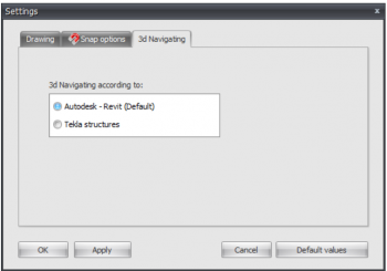
When, in the graphical screen, the cursor comes near a known point and/or an edge, the cursor is automatically placed to this point. There is been snapped to this point.
In much known design programs this functionality is used. It lets you select an exact point.
A very convenient functionality by drawing or displacing a node and/or a beam.
Snap size
The amplitude in mm in which is searched to a known point (node/middle of a beam/ grid line). The default value is set to 150 mm. Generally this value suffices.
Snap to node
Setting whether there needs to be snapped to the nearest node.
Snap to midpoint
Setting whether there needs to be snapped to the midpoint of a beam. A red rectangle is displayed when this point is found.
Snap to grid lines/levels
Grid lines and levels can be used. Here you get to choose whether there needs to be snapped to the intersections. Nodes follow the grid lines and levels. The node will be drawn light grey and follows these lines. At the right bottom of the screen you can see the node coordinates. You can place a node graphically. Obviously you can also numerical change the exact node values afterwards. When you double click on the node, a dialog box is opened. You can also change the node coordinates in this table. When you click on the node, the focus directly lies on the concerning line in the node table.
Snap to existing coordinate lines
All the nodes that are inserted are not directly visualized in the grid lines and levels. This makes snapping possible. This is a very useful functionality. Often the geometry of a construction is regular. Multiple nodes often lie on the same x- or z- coordinate. A construction can be inserted very easy and quick.

