XFEM4U Outer Panels: Difference between revisions
(Created page with " BACK 800 px In XFEM4U you can use the load generator. You can quickly and easily have all wind and/or snow loads generated according to Eurocode. You must first have entered all the outer shells / panels (walls and roof surfaces). All inputted outer panels (shells) are used for the generation of all plane loads for snow and wind. Outer panels are drawn as a "polyline". Exactly as it is also done in AutoCAD, among...") |
No edit summary |
||
| Line 1: | Line 1: | ||
[[Documentation XFEM4U | BACK]] | [[Documentation XFEM4U | BACK]] | ||
[[File:Outer Panel 1.jpg|800 px]] | [[File:Outer Panel 1.jpg|800 px]] | ||
| Line 14: | Line 15: | ||
Beams can optionally be drawn in layers. This corresponds to the functionality of AutoCAD. The layers can be set visible or invisible. (on/off). You can adapt the names of the layers. See Display options | Beams can optionally be drawn in layers. This corresponds to the functionality of AutoCAD. The layers can be set visible or invisible. (on/off). You can adapt the names of the layers. See Display options | ||
===Description=== | ===Description=== | ||
Free text to describe the panel. | Free text to describe the panel. | ||
===Load bearing direction=== | ===Load bearing direction=== | ||
| Line 26: | Line 25: | ||
[[File:Outer Panel 3.jpg]] | [[File:Outer Panel 3.jpg]] | ||
===Surface type=== | ===Surface type=== | ||
Latest revision as of 19:48, 23 August 2022
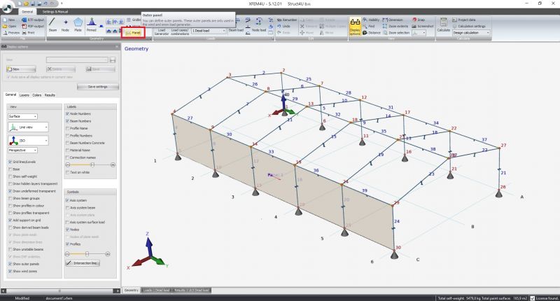
In XFEM4U you can use the load generator. You can quickly and easily have all wind and/or snow loads generated according to Eurocode. You must first have entered all the outer shells / panels (walls and roof surfaces). All inputted outer panels (shells) are used for the generation of all plane loads for snow and wind.
Outer panels are drawn as a "polyline". Exactly as it is also done in AutoCAD, among others. With the escape key or with the right mouse button, you end the drawing.
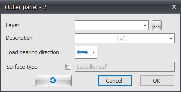
Then the following dialog box is displayed.
Layer
Beams can optionally be drawn in layers. This corresponds to the functionality of AutoCAD. The layers can be set visible or invisible. (on/off). You can adapt the names of the layers. See Display options
Description
Free text to describe the panel.
Load bearing direction
Here you can enter the load bearing direction of the plate you will using.There are 3 options.
Surface type
The different surfaces are automatically detected but here you can also specify the type of surface. You have the choice of: wall, detached wall, flat roof, shed roof, saddle roof and unknown. The type of surface is of course important for the generation of wind loads.
The x-axis of the local coordinate system of the plane load runs from the first point to the second point. With the display option Axis system surface load you can make the local axes system of the panel visible. See XFEM4U UI and settings.
This function allows you to invert the direction of the contour line ("polyline"). By doing so you also influence the coordinate system of the panel.


