Profile
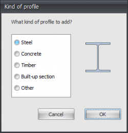
The first time you draw a beam, a profile needs to be chosen / inserted. There is asked what kind of profile you want to add. Also if you want to enter a new profile, you are asked what kind of profile you want to insert.
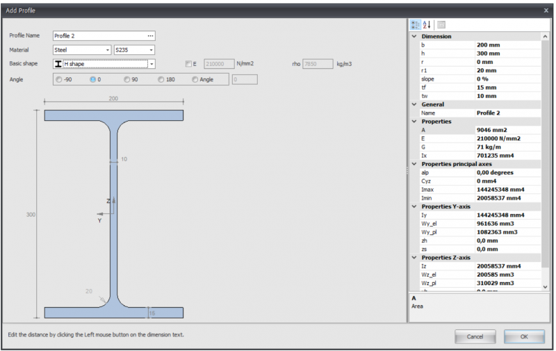
Steel
Remark
You can adapt all profile dimensions by clicking on the relevant values in the dimension lines.
Profile name
You can enter the profile name here, or select a profile from the database. You can also directly type IPE160, HEA200 or HE200A here.
Do you want to enter a common steel profile from the database, click on the 3 dots... at the right side of the input field.
After you have relevant a basic shape, you can subsequently adapt all the profile dimensions by clicking on the concerning numbers in the dimension line. You can also adapt the profile dimensions of the standard profiles by the use of this method.
E
The elasticity modulus, which is adaptable.
Angle
You can rotate the profile within or between.
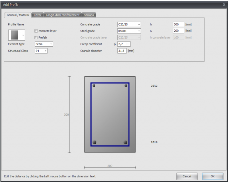
Concrete
Cross sectional shape
You can choose from a large amount of cross sectional shapes. When you have choose a shape, you can subsequently adapt the profile dimensions by clicking on the relevant values in the dimension lines.
Concrete top layer
Setting whether you want to insert an in-situ concrete top layer with a different concrete grade.
Prefab
Setting whether you want to use prefab concrete.
Concrete grade
The concrete grade.
Steel grade
The steel grade of the basic and additional reinforcement.
Creep coefficient
The creep coefficient of concrete. By this coefficient the effective creep coefficient is calculated according to EN 1992-1-1 art. 5.8.4.
You can insert the creep coefficient yourself or you can have it calculated. See Creep. When the creep coefficient is calculated, a detailed calculation according to EN 1992-1-1 B.1 is displayed in the output as well.
Granule diameter
The nominal granule diameter of concrete
Granule diameter
The nominal granule diameter of concrete
h
The height of the concrete cross section in mm
b
The width of the concrete cross section in mm
h concrete layer
The height of the in-situ concrete top layer in mm
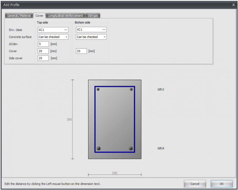
Environmental class
The environmental or exposure class is used for the determination of the required cover. See Exposure classes
Concrete surface
Can be checked, cannot be checked or finished
Delta_Cdev
Execution tolerance of the concrete cover in mm
Cover
Concrete cover top / bottom in mm
Side cover
Side cover left / right in mm
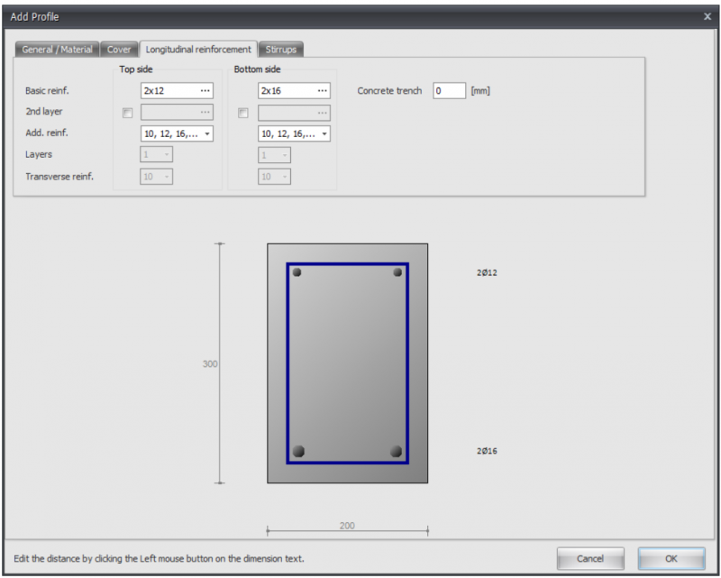
Basic reinforcement
Basic reinforcement top/bottom
Syntax 1: <amount>x<diameter> [+<amount>x<diameter>...]
Syntax 2: <diameter>-<ctc distance> [+<diameter>-<ctc distance>...]
Syntax 3: <mm2> [ / <diameter>]
2nd layer
Basic reinforcement top / bottom in the second layer
Additional reinforcement diameters
The diameters by which the additional reinforcement is designed
Layers
When designing a floor, the option if the basis reinforcement is in the first or in the second layer
Transverse reinforcement
When designing a floor, the diameter of the transverse reinforcement
Concrete trench
Concrete trench in mm
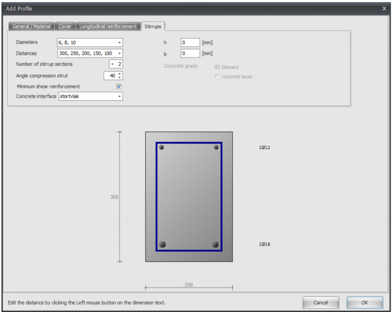
Diameters
Stirrup diameters
Distances
Stirrup distances
Number of stirrup sections
The number of stirrup sections. For shear force this is normally 2.
Angle compression strut
Angle compression strut in degrees
Minimum shear reinforcement
Setting whether the minimum shear reinforcement should be taken in to account.
Concrete interface
In the case of an in-situ concrete top layer, the pouring surface can be entered here.
h
Height of the concrete cross section for the shear force calculation in mm.
b
Width of the concrete cross section for the shear force calculation in mm.
Concrete grade
In case of a in-situ concrete top layer: Concrete grade that needs to be used for the shear force calculation.
Timber
Remark:
You can change the profile sizes by clicking on the relevant values in the dimension line.
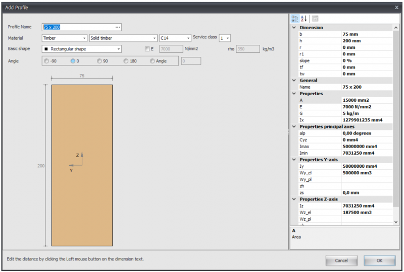
Profile name
Enter the profile name or select a profile from the existing database. You can also directly type 75 x 200 or 75 x 225
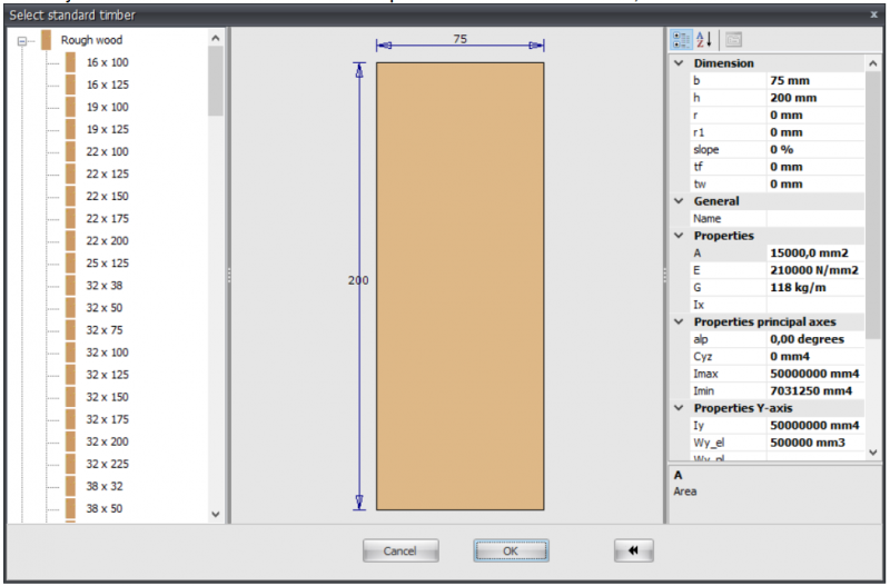
When you want to enter a known timber profile from the database, click on the 3 dots... on the right side of the input field.
Material
Timber
Type of timber
Timber class
Climate class
Basic shape
You can choose from an amount of basic shapes. In this way you can make the profile yourself.
After you selected a basic shape, you can subsequently adapt all the profile sizes by clicking on the concerning values in the dimension line. You can also can adapt the profile sizes of the standard profiles in this way.
E
The elasticity modulus which is adaptable
Angle
You can rotate the profile among an angle
Build-up selection
With this module you can built up any section.
Input
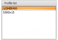
You can Add, Copy and Delete any profiles here. Using Properties you can change your profile or alter the profile dimensions.
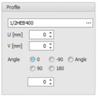
Profile name
Enter the profile name or select from our profile database.
Special input:
- Half H syntax: "1/2 profile name [ - min dimension ]" Example: 1/2IPE300 or 1/2HE650B-5
- Rectangular: syntax: "S width x height" of "F width x height" Example: S200x12
- Hole: syntax: "G width x height" of "H width x height" Example: H50x2
- Round: syntax: "R diameter Example: R50
- Tube(segment): syntax: "R diameter x thickness [ / hoek1 / hoek2 ] " Example: R500x12 or R500x12/0/180
- Trangle: syntax: "D width x height" of "T width x height" Example: T50x60
U
Coordinate u in mm
V
Coordinate v in mm
Angle
Angle in degrees
Graphical input
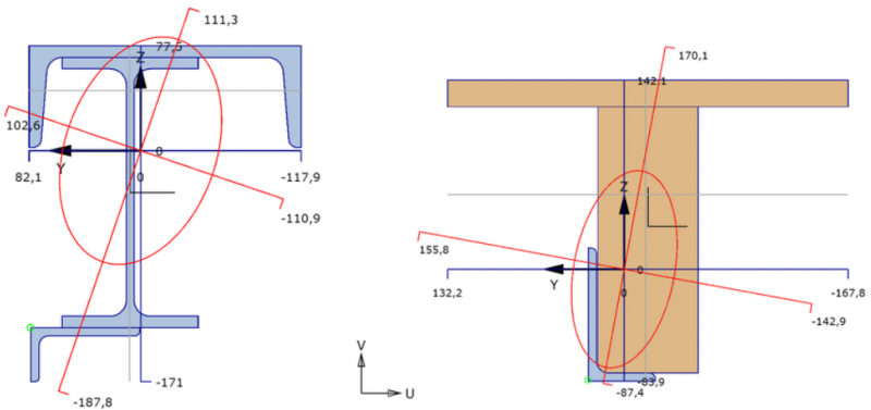
Graphical view of the built up section, with:
- cross section of all profiles use. The focused section is displayed with another color.
- coordinate system
- centroid
- principal axis
- distances from centroid to all largest dimension
- display of radius of gyration
- display of plastic neutral axis
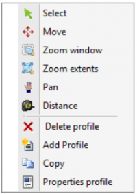
Mouse right click context menu
Menu
Select
you can change the focused profile by left click mouse button within the profile bounds.
Move
Profiles can be moved. There is an automatic snap to known points, which will make moving profile quite easy. You can change the coordinates as well.
Zoom window
With this function you can zoom in on a part of your construction. You can use this by making the graphical input easier.
Zoom extents
With zoom extents the total built up section is shown in full screen.
Pan
By the use of pan you can drag / move a zoomed part of your drawing.
Distance
In this modus distances can be measured.
