XBeam2D Beams
In the graphical screen beams can be added very easy by drawing them. In the function bar you choose this icon: ![]()
Beams are drawn as a 'polyline' just as you know it in AutoCAD. The begin node from a following beam is the end node of the last drawn beam.
It is possible, but not necessary, to draw nodes before you insert the beams. You can also start with drawing the beams, in this way the nodes will be inserted automatically.
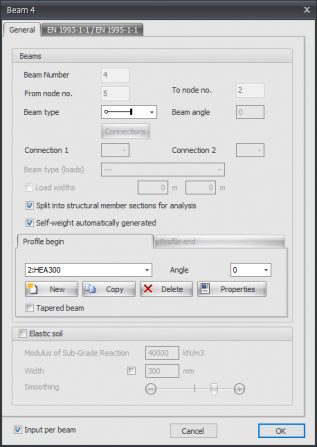
When you draw your first beam, the dialog box shown below appears. In this box you can insert the beam connections and the profile of the beam. Use the escape-key to end the drawing of the beams.
Beam properties
Changing a beam
Changing a beam is possible by clicking on the beam with the left mouse button, and subsequently choose for properties by clicking with the right mouse button. There is a more easy way, namely a double click on the beam. Consequently the following dialog box will be opened.
Beam number
This is the number of the beam.
From node no.
This is the number of the begin node.
To node no.
This is the number of the end node.
Beam angle
This is the angle in degrees with the global x-axis. The direction opposite to the clockwise direction is positive.
Beam type
By the use of the beam type it is shown if the beam in the regarding node is connected by a hinged or a stiff connection.
Connection
Specifically and only for the spring beam connections, the spring data needs to be inserted.
See Spring beam connection
Profile name
Here you choose the profile name
Angle
The angle of the profile. That is the angle relative to the local coordinate system. Normally this is zero degrees. When you want to for example enter the column rotated (so loaded at it's weak axis) you fill in 90 degrees.

You can also add new profiles, copy profiles and delete profiles. Choose for Properties when you want to adapt the profile data and/or want to select another standard profile type from the profile database.
Elastic soil
This enables you to enter a elastic supported beam. The elastic soil is schematized as a number of spring that can support positive reactions only. The spring distance can adjusted with "Smoothing". The spring value of the spring will be calculated automatically.
Modulus of Sub-Grade Reaction
The modulus of Sub-Grade Reaction in kN/m3.
Global values of Sub-Grade Reaction of several types of soil.
| Type | Modulus Sub-Grade [kN/m3] |
|---|---|
| well-graded gravel and gravel / sand mixtures, with little or no fine | 80000 - 130000 |
| poorly graded gravel, with little or no fine | 80000 - 130000 |
| gravel / sand / clay mixtures | 50000 - 130000 |
| well-graded sand and gravely sand, with little or no fine | 50000 - 100000 |
| poorly graded sand, with little or no fine | 40000 - 100000 |
| sand / clay mixtures | 30000 - 80000 |
| very fine sand, loamy sand | 30000 - 50000 |
| solid clay | 10000 - 30000 |
| weak clay and peat | 0 - 10000 |
Width
The width of support. Default is this the width of the used section but it can be adjusted as well. The width is relevant to determine the spring value.
Smoothing
Default the spacing corresponds with 1x section height. It is possible to change this from 0,5x to 5x section height. This value is relevant to determine the spring value.
Input per beam
When this is switched on the dialog above will be displayed each time a new beam is drawn. This for example enables you to switch the profile.
Table Beams
Beams can also be added/changed in the table Beams in the left bottom. It doesn't matter. It is also possible to change in between graphical drawing and numerical input via tables.
Spring beam connection
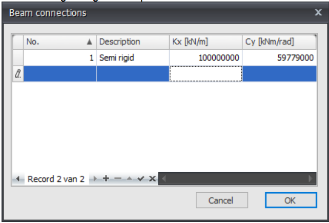
The following dialog box is opened.
Here you can adapt the spring characteristics of a spring connection ( for example a semi-rigid fixed connection)
No.
This is the number of the connection, this number is set automatically. From the beams reference is made to this number. In that way the same connection can be applied multiple times. The spring characteristics are only defined one time. So afterwards adapting the spring characteristics is very easy.
Description
Free text space
Kx
Stiffness in kN/m
Cy
Momentum stiffness in kNm/rad


