XFEM4U UI and settings
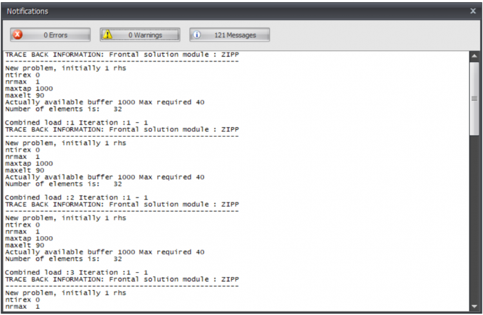
When the force distribution can not be calculated, for instance when the structure is instable, a dialog box is opened. This dialog can be reopened with the button shown above. In this dialog box the notifications of the calculation module are shown.
Calculation settings. See Calculation settings.
Optimize steel profiles.
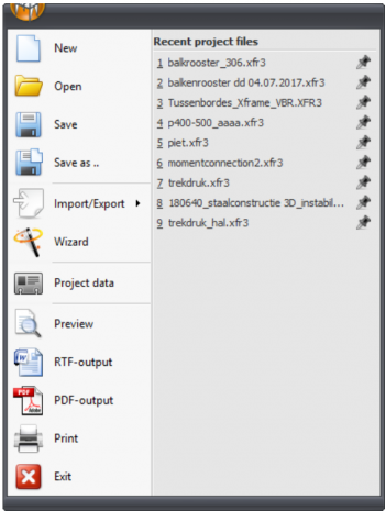
Menu
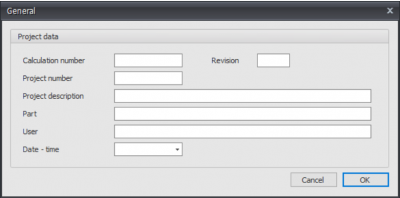
Project data
Preview
Menu: File > Preview
The dialog box of the print preview offers, next to the standard functionality, many extra's including directly creating an e-mail with the calculation in PDF-format attached. From this functionality you can also generate a PDF-file or add a watermark in the output file.
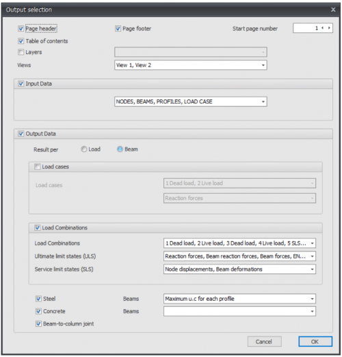
Output selection
Page header
Setting whether the header should be printed
Page footer
Setting whether the footer should be printed
Table of content
Setting whether the table of content should be printed
Drawing
Setting whether a drawing should be displayed at the front page. By standard this is turned off. The drawing resembles the display at the screen.
Layers
You can show certain layers separately in the output
Views
You can select the 3d view images to be added into your output report.
Settings
Tab Settings & Help > Settings
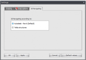
The dialog box settings consists of 5 tabs:
All the inserted values will be saved. When the program is restarted, all the previous entered values will be read and activated.
Apply
Without leaving the dialog box you can see which effect the setting will have on your construction.
Watch out! When you want to apply and save the inserted values definitely, you have to use the button Ok.
Default values
All the values will be reassigned to the default values.
OK
The dialog box is closed and all the inserted values will be implemented and saved.
Cancel
The dialog box is closed and the previous settings will be used.
Snap options
Tab Settings & Help > Settings > tab Snap options
When, in the graphical screen, the cursor comes near a known point and/or an edge, the cursor is automatically placed to this point. There is been snapped to this point.
In much known design programs this functionality is used. It lets you select an exact point.
A very convenient functionality by drawing or displacing a node and/or a beam.
Snap size
The amplitude in mm in which is searched to a known point (node/middle of a beam/ grid line). The default value is set to 150 mm. Generally this value suffices.
Snap to node
Setting whether there needs to be snapped to the nearest node.
Snap to midpoint
Setting whether there needs to be snapped to the midpoint of a beam. A red rectangle is displayed when this point is found.
Snap to grid lines/levels
Grid lines and levels can be used. Here you get to choose whether there needs to be snapped to the intersections. Nodes follow the grid lines and levels. The node will be drawn light grey and follows these lines. At the right bottom of the screen you can see the node coordinates. You can place a node graphically. Obviously you can also numerical change the exact node values afterwards. When you double click on the node, a dialog box is opened. You can also change the node coordinates in this table. When you click on the node, the focus directly lies on the concerning line in the node table.
Snap to existing coordinate lines
All the nodes that are inserted are not directly visualized in the grid lines and levels. This makes snapping possible. This is a very useful functionality. Often the geometry of a construction is regular. Multiple nodes often lie on the same x- or z- coordinate. A construction can be inserted very easy and quick.
