XFEM4U Plates: Difference between revisions
No edit summary |
No edit summary |
||
| Line 169: | Line 169: | ||
===Plate stresses/forces=== | ===Plate stresses/forces=== | ||
See [[Plate stresses/forces]]. | See [[Plate stresses/forces]]. | ||
===Reinforcement=== | |||
See also the background information about the [[Reinforcement calculation plate Eurocode | calculation method.]] | |||
Latest revision as of 10:09, 5 September 2022
General
In the graphical screen slabs can be added very easy by drawing them. Select this item in the function bar.
![]()
Plate egdes are drawn as a 'polyline' just as you know it from AutoCAD.The begin node from a following beam is the end node of the last drawn plate edge.
It is possible, but not necessary, to draw nodes before you insert the plates.
You can also start with drawing the plate edges, in this way the nodes will be inserted automatically.
When you draw your first plate edge, the dialog box shown below appears. In this box you can, among other things, insert the material data of the slab. Use the escape-key or click the right mouse button to end the drawing of the plate edges.
As you are drawing a plate edge, help lines (horizontal and vertical) will appear connected to the previous inserted nodes. Often the node, to which you want to draw the beam, has the same x- or y- or z-value as the previous one. In this way it is easy to insert nodes. Obviously you can adapt the coordinates afterwards numerically or by moving the node.
While drawing a new plate edge, a dimension line parallel to the plate edge in one of the main directions x,y or z will appear. You can, just as you know it from AutoCad, immediately insert the distances numerically by entering the value / values from your keyboard. There are 3 possibilities for drawing a plate edge:
1. Drawing a plate edge with a known length in one of the main directions.
The value will appear in the dimension line. Here you can type in the distance. By the use of the enter-key the input is closed and the plate edge with that length will be added.
2. Drawing a plate edge using relative Cartesian coordinates (dx, dy, dz).
First you enter the distance in x-direction. The value will appear in the dimension line. Thereafter you type a semicolon ";" and the distance in y-direction. The value will appear in a second input field. Next you type a semicolon ";" and the distance in z-direction. The value will appear in a third input field. By the use of the enter-key the input is closed and the plate edge is added.
3. Input of relative cartesian coordinates (dx, dy, dz) or absolute cartesian coordinates (x, y, z).
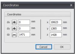
Press the space key and the dialog box below appears. Here you can enter relative coordinates or absolute coordinates directly.
In this way, you can quickly insert your slab/plate.
The plate can be supported in different ways. By Nodes and/or Plate edge.
You can enter Plate loads and/or Node loads.
Reinforcement
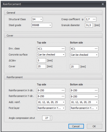
General
Steel grade
The steel grade of the basic and additional reinforcement.
Creep coefficient
The creep coefficient of concrete. By this coefficient the effective creep coefficient is calculated according to EN 1992-1-1 art. 5.8.4.
You can insert the creep coefficient yourself or you can have it calculated. See Creep. When the creep coefficient is calculated, a detailed calculation according to EN 1992-1-1 B.1 is displayed in the output as well.
Granule diameter
The nominal granule diameter of concrete.
Cover
Environmental class
The environmental or exposure class is used for the determination of the required cover. See Exposure classes
Concrete surface
Can be checked, can not be checked or finished
delta_Cdev
Execution tolerance of the concrete cover in mm
Cover
Concrete cover top / bottom in mm
Reinforcement
Reinforcement in X- and Y-direction
Basic reinforcement top/bottom
Syntax 1: <amount>x<diameter> [+<amount>x<diameter>...]
Syntax 2: <diameter>-<ctc distance> [+<diameter>-<ctc distance>...]
Syntax 3: <mm2> [ / <diameter>]
Additional reinforcement diameters
The diameters by which the additional reinforcement is designed
Layers
Setting which reinforcement is in the first layer
Angle compression strut
Shear reinforcement: Angle compression strut in degrees
Holes in plate
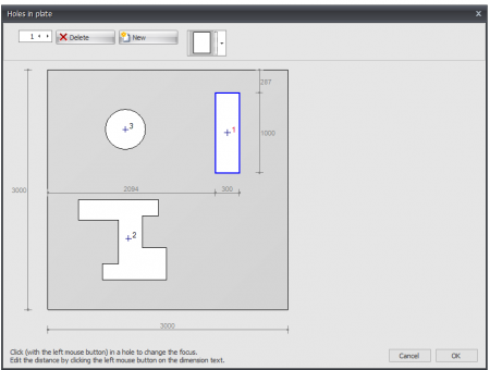
Here you can easily enter holes or openings. You can choose from a large number of basic shapes that are parameterized.

The position and dimensions of the hole or opening can be adjusted by clicking on the relevant dimension line. The focus in case of multiple holes can be changed by clicking with the left mouse button in the hole contour. If you hold down the left mouse button and move the mouse, you can move the hole graphically. It checks whether holes overlap or cut through the outer contour.
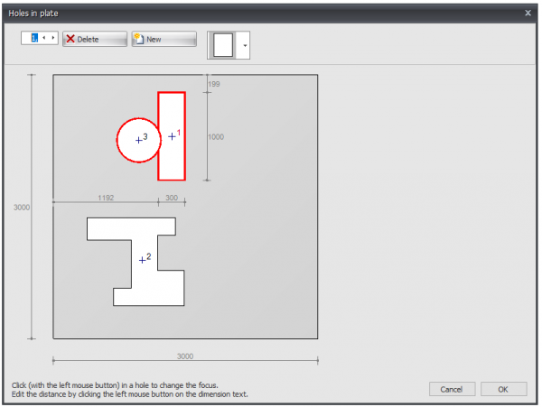
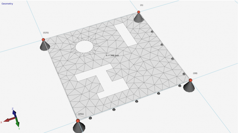
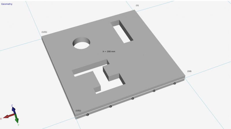
Plate edge
Plate edges are drawn as transparent tubes. By double-clicking on a plate edge (or 1 click right mouse button > Properties) the dialog box below becomes visible.
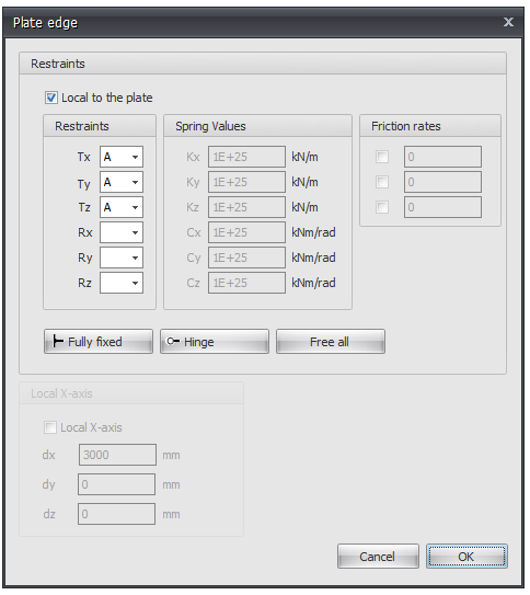
Local to the plate
Setting whether the supports are to be introduced in relation to the local axle system of the plate.
Supports / Restraints
Here you enter how the plate edge is supported. There are many possibilities.
You can use the most common / standard supports:
Fully fixed Tx=A(Absolute), Ty=A, Tz=A, Rx=A, Ry=A, Rz=A. (That is the default setting)
Hinged Tx=A, Ty=A, Tz=A. No moments can be transmitted, only transverse and normal forces.
Spring support
You can also enter a spring support. Tx=S(Spring), Ry=S and/or Rz=S. You also give the spring value Kx, Cy and/or Cz in kN/m or kNm/rad.
Local x-axis see Local coordinate system
Plate stresses/forces
Reinforcement
See also the background information about the calculation method.
