XFEM4U Loads: Difference between revisions
No edit summary |
No edit summary |
||
| Line 415: | Line 415: | ||
By standard there are three load combinations generated. ULS 6.10a, ULS 6.10b and SLS | By standard there are three load combinations generated. ULS 6.10a, ULS 6.10b and SLS | ||
=== | ===Sequence load combinations=== | ||
With the right mouse button the following context menu is opened. With these functions you can easily adapt the sequence of the load combinations, or insert new load combinations. | With the right mouse button the following context menu is opened. With these functions you can easily adapt the sequence of the load combinations, or insert new load combinations. | ||
Revision as of 20:34, 15 August 2022
Every load (node load, beam load or node displacements) are inserted per load case.
Load cases
Input of the load cases.
No.
This number is generated automatically. You can not change this number
Description
Free text to describe the load case
Type
The type of load. Dependent on the type of load, standard combination factors (frequent / quasi-permanent value ) psi0, psi1, and psi2 are determined according to the Eurocode.
These combination factors are offered as a standard by entering the load combinations. However, these values can be adapted.
Automatically two load combinations are generated. Permanent and variable loads.
Automatically generate combinations
When you enter/change load combinations, the load combinations are automatically generated. You can also change these combinations and expand them.
Permanent load favorable
Extra ULS load combinations are generated in which the load factor for the permanent load is 0.90.
Sequence load case
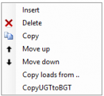
With a click on the right mouse button, the context menu shown below is opened. With these functions you can easily adapt the sequence of the load cases and/or insert load cases.
Insert
A new load case is created, and inserted above the current load case.
Delete
The load case is deleted, including all the loads
Copy
The load case is copied, including all the loads
Move up/ move down
A load can be moved up and down a line.
Copy load case
With the right mouse button the following context menu is opened.
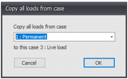
Copy loads from...
Every load from an already existing load case can be copied. The dialog box shown below is opened. Herein you choose the load case from which you want to copy the loads.
Beam loads
Beam loads are inserted in a local beam coordinate system. See Design arrangement.
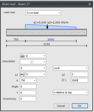
The dialog box shown below is opened.
Load case
Choice for the load case.
Type of load
Choose the type of load you want to add.
| Type | Description |
|---|---|
| Even distributed load, or varying load | |
| Point force - F-load | |
| Moment - M-load |
Description
Free text to describe the load.
Direction of the load/ local global
The load can be inserted in 3 directions. In x-,y- or z-direction relative to the local coordinate system standard or the global coordinate system.
q1
The magnitude of the load. For the q-load the magnitude of the load at the beginning in kN/m. For a point load the amplitude of the load in kN. For a moment the magnitude of the load in kNm.
With plus min you can change the sign of the loads very easy. Standard the sign is at min because this is most common
q2
Only for the q-load the magnitude of the load at the end of the beam in kN/m.
a
The distance in mm where the load starts, counted from the begin node of the beam.
L
Only for the q-load the length of the load should be inserted. Standard the load is going up to the end of the beam.
Angle
Only for the q- and F-load. The angle in degrees to the perpendicular. The direction opposite to the clockwise direction is positive.
z
The distance in the z-direction in mm relative to the reference line. The reference line is adjustable. 'z relative to top', 'z relative to centerline', 'z relative to bottom'.
This distance is only relevant for lateral-torsional buckling resistance check
Eccentricity
The eccentricity in mm measured perpendicular to the load load surface. For a load in the z-direction this is the distance in y-direction. For a load in the y-direction this is the distance in the z-direction. This eccentricity causes torsion in the beam. By standard the eccentricity is zero. For example with piled concrete foundations the load can be eccentric.
Table
Beam loads can also be added/changed in the table. It does not matter. It is also possible to change in between graphical input and numerical input via tables.
Node loads
Node loads are added in the Node coordinate system. See Design Arrangement.
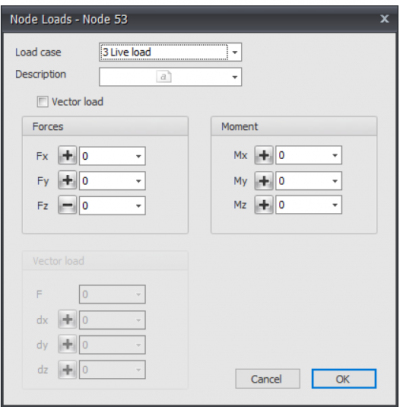
The dialog box shown below is opened.
Load case
Option for the load case.
The node load will be inserted in the global coordinate system. When for the particular node, a local coordinate system is inserted, the forces will be inserted relative to this coordinate system.
Description
Free text to describe the load.
Fx
The magnitude of the force in kN in the x-direction
Fy
The magnitude of the force in kN in the y-direction
Fz
The magnitude of the force in kN in the z-direction
Mx
The magnitude of the moment in kNm around the x-axis.
My
The magnitude of the moment in kNm around the y-axis.
Mz
The magnitude of the moment in kNm around the z-axis.
Vector load
An opportunity for entering the load as a vector in a certain direction.
F
The magnitude of the vector force in kN
dx
Relative distance in x-direction
dy
Relative distance in y-direction
dz
Relative distance in z-direction
By the use of dx,dy and dz the direction of the vector force is determined.
Table
Node loads can also be added/changed in a table. It does not matter. It is also possible to change in between graphical input and numerical input via tables
Node displacements
Node displacements are added in a node coordinate system. See Design arrangement.
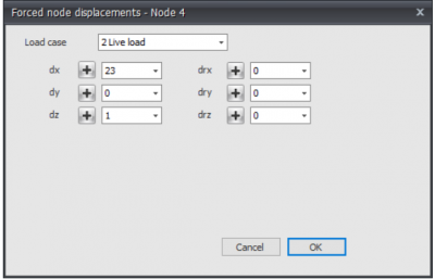
The dialog box shown below is opened.
Load case
Option for the load case.
The node displacement will be inserted in the global coordinate system . When for a particular node, a local coordinate system is inserted, the displacement will be inserted relative to this coordinate system.
dx
The amplitude of the displacement in mm in the x-direction
dy
The amplitude of the displacement in mm in the y-direction
dz
The amplitude of the displacement in mm in the z-direction
drx
The amplitude of the rotation in mrad around the x-axis
dry
The amplitude of the rotation in mrad around the y-axis
drz
The amplitude of the rotation in mrad around the z-axis
Table
Node displacements can also be added/changed in a table. It does not matter. It is also possible to change in between graphical input and numerical input via tables.
Surface loads
Surface loads can be used for plates, walls and beam structures. In the case of beam structures, all beam loads are generated automatically.
You can draw any surface as a 'polyline' just as you know it from AutoCAD. Press the escape-key or click the right mouse button when finished.
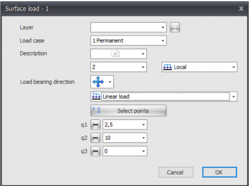
Next the dialog box shown below is opened.
Pay attention! To be able to generate beam loads, edge beams must occur.
With the display option Show derived bar loads you can display all automatically generated beam loads. You can use this to check whether the loads have been created correctly. See Display Options.
Load case
Choice for the load case.
Description
Free text to describe the load.
Direction of the load/ local-global
The load can be inserted in 3 directions. In x-,y- or z-direction relative to the local coordinate system(standard) or the global coordinate system.
You can choose "Local", "Global" and "Global projective".
When choosing Global projective for snow and live loads the load is related on the projection area
q1 ,q2 and q3
The magnitude of the load in kN/m2.
Load bearing direction
Here you can enter the load bearing direction of the plate you will using. There are 3 options.
Type of load
Here you can specify whether the load is uniformly distributed or linear. With a linear running load you can enter, for example, a water pressure or soil pressure on a wall. Or a running wind load over a tall building.
Linear loads are defined by specifying loads q1, q2 and q3 in 3 points. The button below allows you to select those 3 points of the "polyline".
All directions, parallel to x-direction and parallel to y-direction, related to the axis of the surface load. The x-axis is from first point towards the second point you will draw.
You can view the local coordinate system with display option Surface load orientation. See Display Options.
Load combinations
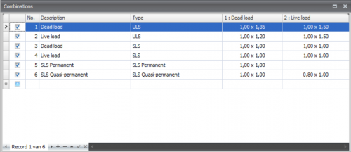
Input of load combinations
Checkbox
Setting whether the combination is to be calculated or not
No.
This number is automatically generated. You can not change this number.
Description
Free text space to describe the load combination
Type
The type of load ULS - ultimate limit state, ULS- fire, SLS-serviceability limit state, quasi permanent.
Dependent on the type of combination, standard values for the combination factors psi and the load factor gamma are offered according to the Eurocode. These values can be adapted.
Columns with load cases
For all the load cases, columns are created. In that way, a table appears in which all the combinations are shown. Every cell contains 2 values in the syntax: combination factor x load factor.
When you click on a cell the following dialog box appears. Here you can adapt both values.
For the combination factor and the load factor combo-boxes are offered including the standard values from which you can choose. You can also insert an own value. This gives a lot of freedom.
If you for instance take one of the values as zero, the product of the two values obviously is zero as well. In that case the cell is showed 'empty'. This is only to make things clear.
By standard there are three load combinations generated. ULS 6.10a, ULS 6.10b and SLS
Sequence load combinations
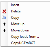
With the right mouse button the following context menu is opened. With these functions you can easily adapt the sequence of the load combinations, or insert new load combinations.
Insert
A new load combination is created and inserted above the current load case.
Delete
The load combination is deleted.
Copy
The load combination is copied.
Move up/ move down
A load combination can be moved up and down a line.
Copy ULS combination to SLS
Every load combination of the type ULS will be copied as type SLS. The load factors are set to 1.00

