XBeam2D Nodes: Difference between revisions
No edit summary Tag: visualeditor |
No edit summary Tag: visualeditor |
||
| Line 1: | Line 1: | ||
[[Documentation XBeam2D|BACK]] | |||
===Nodes=== | ===Nodes=== | ||
Latest revision as of 08:52, 12 November 2022
Nodes
Nodes can easily be added in the graphical screen. To do this, you have to choose ![]() in the menu bar. In these modus you can add multiple nodes by means of the left mouse button. By placing the node, you will see the coordinates in the right bottom.
in the menu bar. In these modus you can add multiple nodes by means of the left mouse button. By placing the node, you will see the coordinates in the right bottom.
Supports are linked to the nodes. They can be set within the node properties.
Changing a node
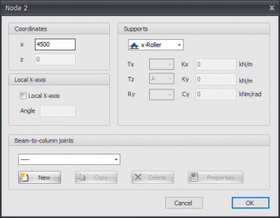
Changing a node is possible by clicking on the node by use of the left mouse button, and subsequently choose for properties by clicking on the right mouse button. There is a more easy way, namely a double click on the node. Consequently the following dialog box will be opened.
Coordinates
x
x-coordinate
Local x-axis see Local coordinate system
Table Nodes
Nodes can also be added / changed in the table Nodes. It does not matter. It is also possible to change in between graphical input and numerical input via tables.
Internal hinge
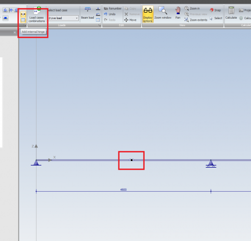
In these modus you can add multiple internal hinges by use of the left mouse button. By placing the node the coordinates are shown in the right bottom. This is shown in the image below.
When you add an internal hinge, a new node in the beam is generated, and the regarding beam is automatically separated into two beams with a hinge connection. Possible beam loads will also be equally distributed or separated.
In this way you can easily design a gerber beam.


