Background Information and Theory: Difference between revisions
No edit summary Tag: visualeditor |
No edit summary Tag: visualeditor |
||
| Line 27: | Line 27: | ||
[[File:SteelJointRigidity.png]] | [[File:SteelJointRigidity.png]] | ||
== Ponding == | |||
Latest revision as of 19:50, 22 April 2023
Tapered beam
You can optionally enter a tapered beam. The tab "Profile end" is activated. Here you can enter the 2nd profile at the end of the bar. Attention! The basic shape of the profile (H-, U-, L-shape, etc.) must match that of the profile at the beginning of the beam.
Analysis
For the mechanics calculation, the beam is automatically divided into a number of beam parts with a length corresponding to the average profile height. The profile section properties such as moment of inertia are calculated in the middle of each beam part. A constant moment of inertia is calculated for each beam part. Because the beam parts are quite short, this approach proves to be sufficiently accurate.
Stress testing
For stress testing, the profile section properties are calculated per section (per x-distance). Thus, this calculation is exact.
Calculation Steel Joints rigidity
Load-dependent rotational rigidity
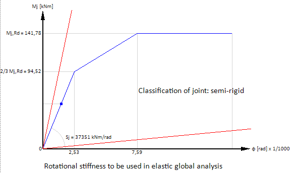
In XFEM4U and XFrame2D a geometric nonlinear analysis (GNL) is calculated by standard. The analysis is determined iteratively. The beam-column moment connections can be entered. The rotational stiffness of all connections per iteration step is determined. Based on the occurring moment in the beam connection, the rotational rigidity diagram of the designed connection (see diagram below) determines a rotational stiffness or spring stiffness which is then used in the next iteration step. The iteration stops when there are no more changes in the analysis.
In XFEM4U and XFrame2D, a load-dependent rotational rigidity is therefore taken into account for all moment connections. This gives the most accurate result and leads to an economically optimal design.
At small moments (under 2/3 Mj, Rd), initial rotational stiffness Sj, ini is calculated. At larger moments with the rotational stiffness Sj corresponding to the bending moment Mj, Ed, the trilinear rotational rigidity diagram is used. See the diagram below.
